
Pipeline compensator

A pipeline compensator and ring pipe technology, applied in the field of compensators, can solve problems such as corrosion cracking, compensator damage, guide sleeve wear, etc., and achieve the effects of prolonging service life, improving service life and reducing corrosion

Inactive Publication Date: 2013-09-18
李春光 +1
View PDF7 Cites 0 Cited by
  • Summary
  • Abstract
  • Description
  • Claims
  • Application Information

AI Technical Summary

Problems solved by technology

However, the problem of corrosion of corrosive media and the wear of dusty media on the inlet of the guide ring cannot be well resolved.
Therefore, when encountering a comprehensive environment, the compensator cannot achieve the ideal design service life
Especially when there is a dusty corrosive medium circulating in the compensator pipe, although the inner wall of the metal compensator's diversion tube will add a high-temperature resistant layer or a corrosion-resistant layer, due to the functional limitations of the metal bellows of the metal compensator itself , the medium in the guide tube can still flow into the metal bellows. Under the action of high temperature and high pressure, the corrosive molecules in the corrosive medium will corrode the metal bellows very seriously, and the corrosion of the metal bellows by the medium will seriously affect the performance of the pipeline compensator. service life
Moreover, the working conditions of high flow rate and high dust concentration of dusty medium will aggravate the damage of the compensator, resulting in wear of the guide sleeve, pitting corrosion and perforation of bellows, and stress corrosion cracking, and even medium leakage, partial or overall pipe network shutdown run
[0003] Therefore, the present invention proposes a pipeline compensator with high temperature resistance, corrosion resistance and wear resistance, which can overcome the deficiencies of existing metal compensators and is suitable for the following conditions: temperature 250°C, various dusty media, and various corrosive molecules pipeline

Method used


Image

  • Pipeline compensator
  • Pipeline compensator

Examples


Embodiment Construction

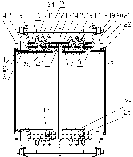
[0023] Such as figure 1 , 2 As shown, a pipeline compensator provided by the present invention first declares that the medium flow direction of the pipeline compensator is figure 1 From left to right in the figure, so the left side in the figure is called the front side or the front, and the right side in the figure is the rear side or the rear. The installation direction of the pipeline compensator is figure 1 In the reading direction, the upper side in the figure must be installed upwards.

[0024] Depend on figure 1 It can be seen that the pipeline compensator has a front ring plate 5 and a rear ring plate 6 connected in series by several large pull rods 19. The inner end of the front ring plate 5 is welded to a front connecting pipe 1, and the front connecting pipe 1 is connected with a fixing method. Lan 4, the inner end of the rear ring plate 6 is welded with a rear connecting pipe 22, and the rear connecting pipe 22 is connected with a loose flange 21; The first rin...


PUM


Abstract

The invention relates to a pipeline compensator provided with a flow-guiding sleeve and a metal bellows which are both arranged along the horizontal direction. The rear end of the flow-guiding sleeve is provided with a ventilating ring gap communicated with the metal bellows. The pipeline compensator is characterized in that a sealing pipe structure arranged along the horizontal direction is positioned between the flow-guiding sleeve and the metal bellows, a seal cavity is formed between the metal bellows and the sealing pipe structure, the sealing pipe structure is provided with an extensible rubber bellows, the top side and the bottom side of the sealing pipe structure are respectively provided with check valves, the lower portion of each check valve is provided with a check valve opening, and the lower portions of all the check valves are tightly connected with the sealing pipe structure. When a medium circulates in the pipeline compensator, due to the seal cavity, a medium corroding the metal bellows is only a non-flowing medium in the seal cavity, corrosion to the metal bellows caused by corrosion molecules in a pipeline medium is reduced, and accordingly the service life of the pipeline compensator is prolonged.

Description

technical field [0001] The invention relates to a compensator, in particular to a corrugated pipeline compensator. Background technique [0002] The corrugated pipe compensator is a commonly used pipe compensator. Because of the requirements of the working environment, people continue to improve it in order to improve its service life. However, the problem of corrosion of corrosive media and the wear of dusty media on the inlet of the guide ring cannot be well resolved. Therefore, when encountering a comprehensive environment, the compensator cannot achieve the ideal design service life. Especially when there is a dusty corrosive medium circulating in the compensator pipe, although the inner wall of the metal compensator's guide tube will add a high temperature resistant layer or a corrosion resistant layer, due to the limitation of the function of the metal bellows of the metal compensator itself , the medium in the guide tube can still flow into the metal bellows. Under ...

Claims


Application Information

Patent Timeline
Patent Type & Authority Patents(China)
IPC IPC(8): F16L51/03F16L58/18F16L57/04F16L59/21
Inventor 李春光孙占友
Owner 李春光
Learn More