
Minitype turbofan engine

A turbofan engine, micro technology, applied in the direction of machine/engine, jet propulsion, etc., can solve the problems of increased wear and tear of parts, large combustion chamber space, inability to start by itself, etc., to achieve low noise, small combustion chamber space, and efficiency. improved effect

Inactive Publication Date: 2013-11-13
张海涛
View PDF6 Cites 0 Cited by
  • Summary
  • Abstract
  • Description
  • Claims
  • Application Information

AI Technical Summary

Problems solved by technology

This type of engine has the following characteristics when working: (1) The fuel supply method of this type of engine is to spray directly into the combustion chamber without atomization, and the fuel is atomized by the high temperature generated in the combustion chamber of the engine working chamber, so it cannot start automatically when starting , it is necessary to provide high-pressure combustible gas into the combustion chamber first and then ignite it with a manual igniter to make the turbine and compressor run, and use the temperature of the combustible gas to atomize the fuel. The atomized fuel can only be started successfully after continuous combustion. , if the startup is unsuccessful, the fuel that has been injected into the combustion chamber is still in a liquid state because it has not been atomized, causing the engine to be rich in oil. If it is not handled properly, it will easily cause a fire, and the startup operation is complicated at the same time
(2) In the actual work of this type of engine, due to the small number of compressor stages, large combustion chamber space, and small compression ratio, in order to pursue greater thrust, it is necessary to increase the rotor speed. According to data, the maximum speed of this type of engine can be It can reach 130,000 rpm, which will not only greatly increase fuel consumption, but also increase the wear and tear of various parts, and greatly shorten the service life. The current type of engine needs to be returned to the factory for maintenance after 30 hours of use.

Method used


Image

  • Minitype turbofan engine
  • Minitype turbofan engine

Examples


Embodiment Construction

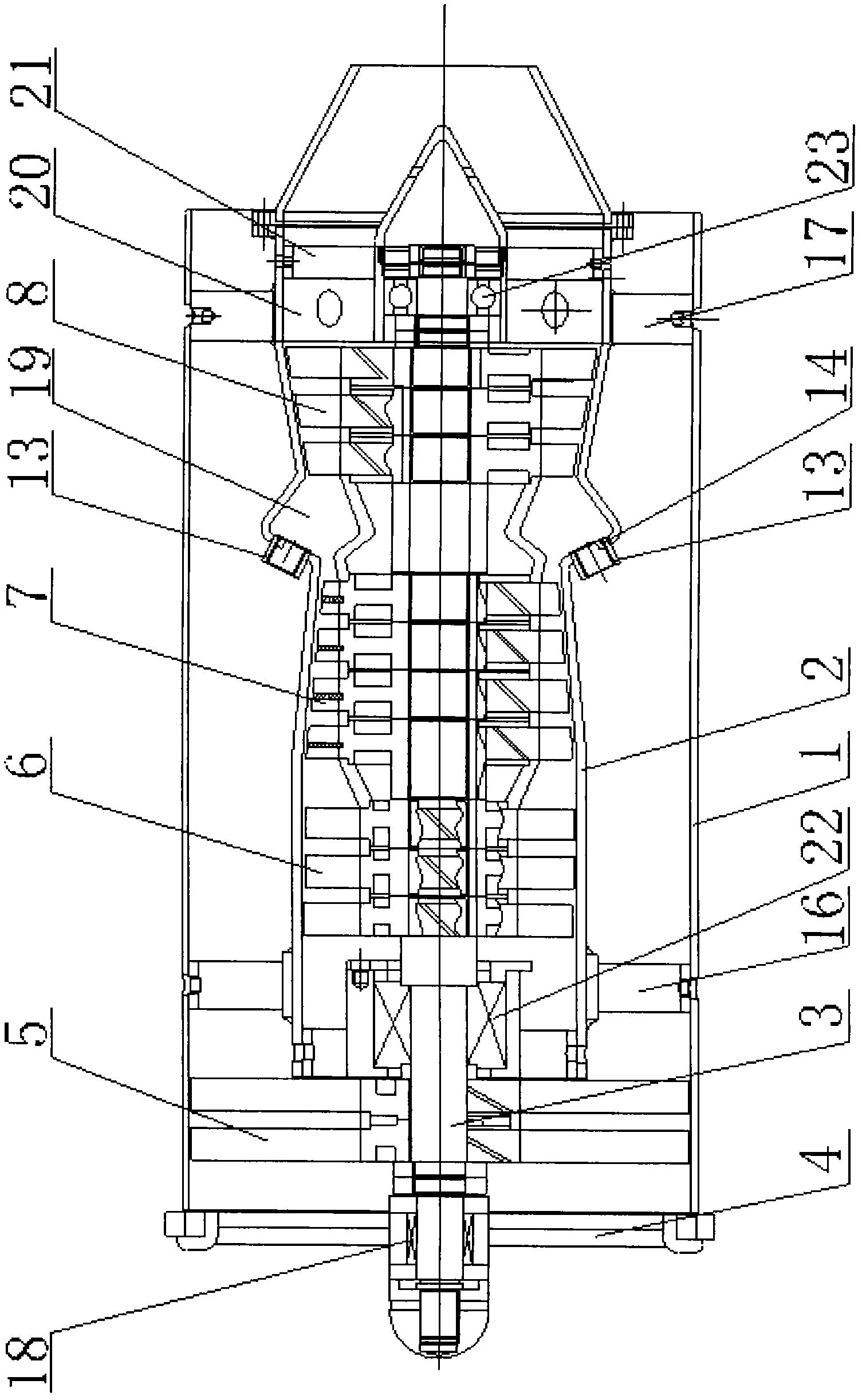
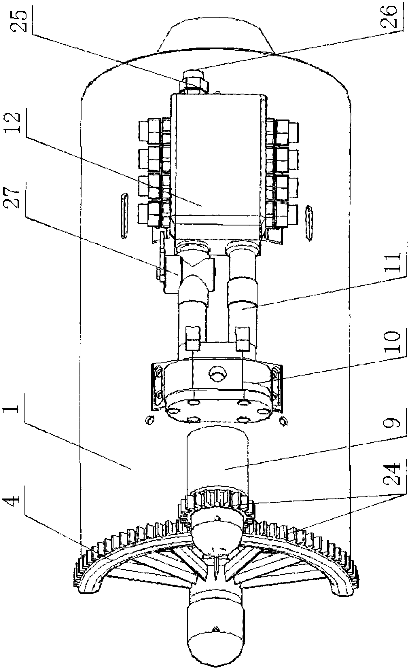
[0019] Please refer to the attached figure 1 And attached figure 2 Shown, the present invention is a kind of miniature turbofan engine, and it is made up of outer duct 1, interior duct 2, main shaft 3, inlet guide vane 4, fan 5, medium pressure compressor 6, high pressure compressor 7, turbine 8, The starter motor 9, the first oil distributor 10, the atomizing fuel injector 11, the second oil distributor 12, the fuel injector 13 and the spark plug 14 are assembled and formed.

[0020] Wherein, the inner duct 2 is installed in the outer duct 1 through a front bracket 16 of the outer duct and a rear bracket 17 of the outer duct.

[0021] The inlet guide vane 4 is located at one end of the outer duct 1 , and is mounted on the main shaft 3 through a one-way bearing 18 .

[0022] The fan 5, the medium-pressure compressor 6, the high-pressure compressor 7 and the turbine 8 are sequentially held on the main shaft 3 and rotated by the main shaft 3, and the holding method is specifi...


PUM


Abstract

The invention relates to a minitype turbofan engine comprising an outer bypass, an inner bypass, a main shaft, an air inlet guide vane, a fan, an intermediate pressure air compressor, a high pressure air compressor, a turbo machine, a start motor, a first oil distributor, atomization oil spray nozzles, a second oil distributor, oil spray nozzles and a spark plug. The inner bypass is installed in the outer bypass; the air inlet guide vane is installed on the main shaft; the fan, the intermediate pressure air compressor, the high pressure air compressor and the turbo machine are fixedly held on the main shaft; the main shaft is supported on the inner bypass; a combustion chamber is formed between the high pressure air compressor and the turbo machine; the start motor is engaged with the air inlet guide vane; the first oil distributor, the atomization oil spray nozzles and the second oil distributor are sequentially connected; a joint is installed on the second oil distributor and is connected with the oil spray nozzles; and the spark plug is positioned at one end of the combustion chamber. The minitype turbofan engine has the advantages of being low in noises, good in hidden performance, high in unit power, easy in start and operation, long in service life, and the like.

Description

【Technical field】 [0001] The invention relates to a power device, in particular to a micro turbofan engine, which belongs to the technical field of engines. 【Background technique】 [0002] There are two kinds of power units of small-sized aviation equipments such as aviation models of the prior art, target drones, unmanned aerial vehicles, aerial detection, and aerial photography: a kind of is a small piston engine; the other is a miniature or small turbojet engine. [0003] However, the small piston engine has the disadvantages of large weight, small power output and low weight ratio, and it has the disadvantages of low endurance and high noise when used as the power of the aircraft model; the power is insufficient, and the maneuverability is not good when used as a target aircraft, so it cannot Simulate the real combat form; as UAVs and aerial detection equipment, sometimes due to the loud noise, the concealment is not good. [0004] The compression method of the micro or...

Claims


Application Information

Patent Timeline
Patent Type & Authority Patents(China)
IPC IPC(8): F02K3/00
Inventor 张海涛
Owner 张海涛
Learn More