Locking device used for injection moulding machine

A locking device and mold technology, applied in the field of locking devices, can solve the problems of long distance from the locking device and high cost of the driving unit

Active Publication Date: 2012-07-18
ENGEL AUSTRIA
View PDF9 Cites 2 Cited by
  • Summary
  • Abstract
  • Description
  • Claims
  • Application Information

AI Technical Summary

Problems solved by technology

The disadvantage here is that the drive unit for the piston is relatively far from the locking device
Furthermore, the translational return movement after reaching the maximum position or dead point requires a relatively high force

Method used


Image

  • Locking device used for injection moulding machine
  • Locking device used for injection moulding machine
  • Locking device used for injection moulding machine

Examples


Embodiment Construction

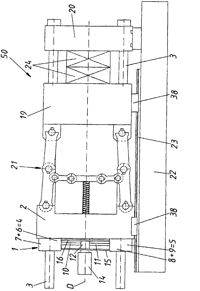
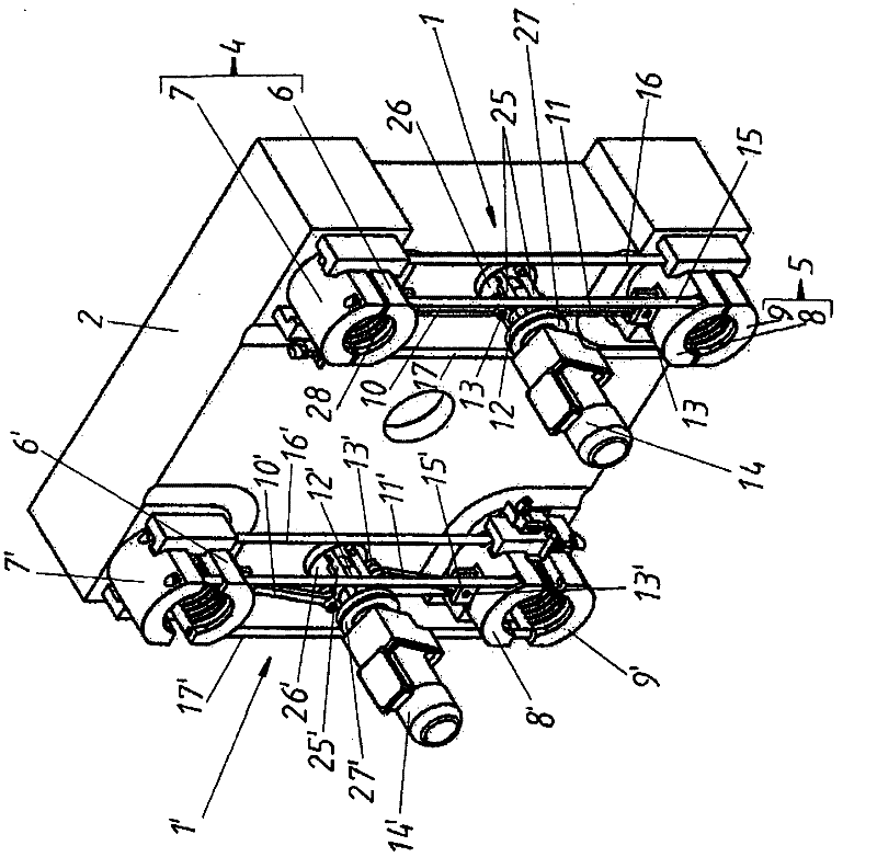
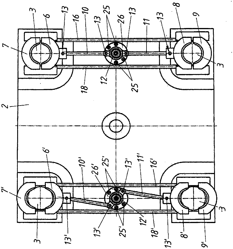
[0024] figure 1 Overall, a view of an injection molding machine 50 is shown, comprising a mold half 24 clamped between a stationary mold clamping plate 20 and a movable mold clamping plate 19 . A crank mechanism 21 is arranged between the movable mold clamping plate 19 and the end plate 2 . The movable mold clamping plate 19 and the end plate 2 are each mounted movably via slides 38 on guide rails 23 of the frame 22 of the injection molding machine 50 . All three plates 2 , 19 and 20 are passed through by a total of four crossbeams 3 , wherein the locking device 1 is shown schematically at the end of the crossbeams 3 on the plate side. This locking device 1 is mounted on the end plate 2 and holds the end plate 2 fixedly on the beam 3 by clamping together the half shells 7 and 6 or 8 and 9 of the clamping elements 4 or 5 . In order to be able to synchronize the two clamping elements 4 and 5, on the one hand the known per se rods 16 and 15 (as well as the connecting rods 17 an...


PUM


Abstract

The present invention relates to a locking device used for an injection moulding machine, i.e., a locking device (1) used for locking an end plate (2) or a mould clamping plate (19) on at least two different positioned beams (3) of the injection moulding machine through at least two clamping elements (4 or 5). The clamping element are respectively configured for one of the different positioned beams (3), and respectively have at least two half-shell (6, 7 or 8, 9), wherein, at least two half-shells (6, 8) configured for the different positioned beams (3) are hinged to a common synchronism element (12) respectively through rod pieces (10, 11), the two rod pieces (10, 11), on one hand, are connected with the corresponding half-shells (6, 8), on the other hand, with the common synchronism element (12) through a rotational joint (13), wherein, the synchronism element (12) is rotatable.

Description

technical field [0001] The invention generally relates to a locking device for locking an end plate or a mold clamping plate on at least two differently positioned cross members of an injection molding machine by means of at least two clamping elements, which are respectively configured One of the differently positioned beams and each having at least two half shells. Background technique [0002] The invention therefore relates to a locking device which clamps or holds an end plate (or clamping plate) on a cross member of an injection molding machine. For this purpose, various locking devices have been known for many years. [0003] For example, JP 29 89 116 shows a locking device with a hydraulically driven lifting cylinder which moves the half-shells of the two clamping elements in translation. [0004] In EP 1 238 777 B1 the synchronization of the individual clamping elements of the locking device is achieved in a very similar manner. Here, however, the individual half...

Claims


Application Information

Patent Timeline
Patent Type & Authority Applications(China)
IPC IPC(8): B29C45/64
CPCB29C45/6728B29C45/1775B29C45/66
Inventor H·蔡德尔霍费尔G·肖特
Owner ENGEL AUSTRIA
Why Eureka
Try Eureka