Infrared receiving circuit input structure

A technology of infrared receiving and input structure, which is applied in electromagnetic receivers, electromagnetic wave transmission systems, electrical components, etc. It can solve the problems of circuit sensitivity and receiving distance influence, unable to input differential voltage signals normally, front-end amplifier saturation distortion, etc.

Inactive Publication Date: 2012-07-11
CRM ICBG (WUXI) CO LTD
View PDF8 Cites 5 Cited by
  • Summary
  • Abstract
  • Description
  • Claims
  • Application Information

AI Technical Summary

Problems solved by technology

[0018] The technical problem to be solved by the present invention is to solve the problem of saturation distortion of the front-end amplifier and the inability to normally input the differential voltage signal in a strong light environment without increasing the total resistance value of the I-V conversion circuit, and to make the sensitivity of the circuit and the receiving distance unaffected. influences

Method used


Image

  • Infrared receiving circuit input structure
  • Infrared receiving circuit input structure
  • Infrared receiving circuit input structure

Examples


Embodiment Construction

[0034] In order to make the object, technical solution and advantages of the present invention clearer, the present invention will be further described in detail below in conjunction with the accompanying drawings.

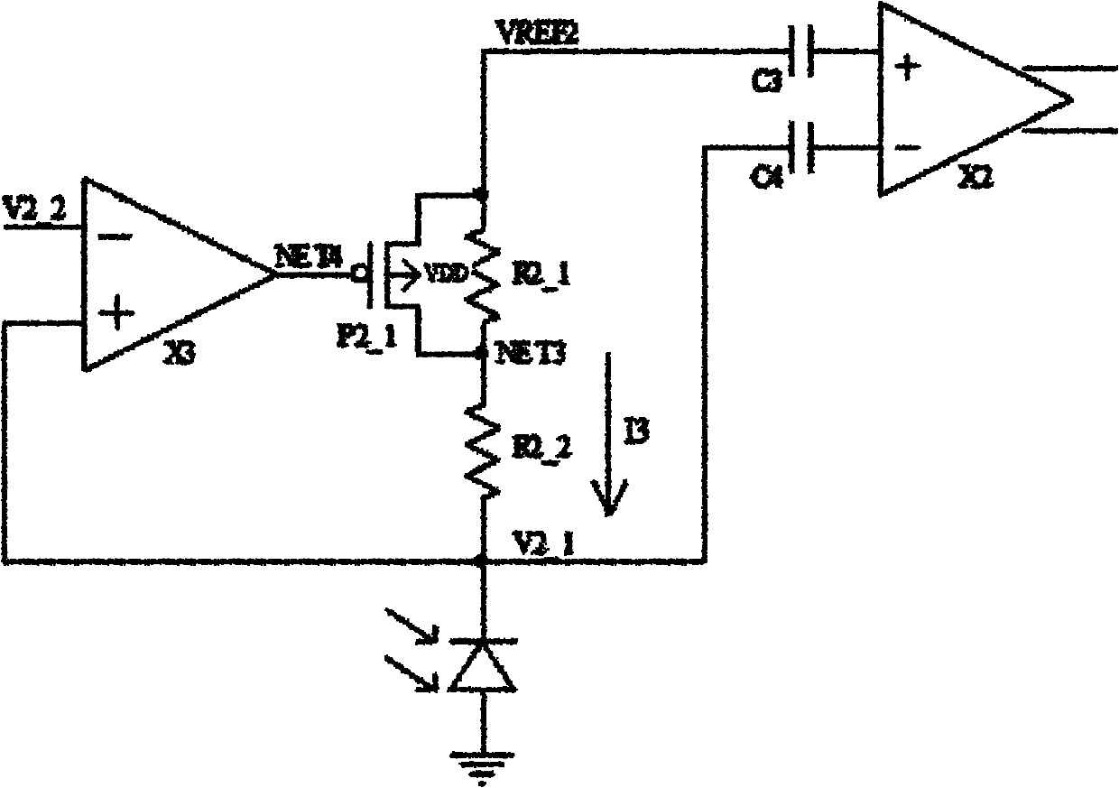
[0035] image 3 The circuit diagram of the first embodiment of the input structure of the infrared receiving circuit provided by the present invention.

[0036] Such as image 3 As shown, the circuit connection relationship is: the drain terminal of PMOS transistor P2_1 is connected to voltage VREF2, the gate is connected to node NET4, the source is connected to node NET3, and the substrate is connected to voltage VDD; one terminal of resistor R2_1 is connected to voltage VREF2, and the other terminal is connected to node NET3; one end of resistor R2_2 is connected to node NET3, and the other end is connected to voltage V2_1; one end of photodiode is connected to voltage V2_1, and one end is grounded; voltage VREF2 and voltage V2_1 are respectively connected to c...


PUM


Abstract

The invention discloses an infrared receiving circuit input structure, which comprises a photosensitive diode and one or a plurality of voltage division circuits and is characterized in that the voltage division circuit comprises a control circuit, a switch circuit and a resistance network, wherein the control circuit is connected with the switch circuit and controls the on-off state of the switch circuit; the switch circuit is connected with the resistance network in parallel; and the control circuit and the resistance network are respectively connected into an infrared receiving circuit to form a feedback loop. By adopting the structure, the problem of saturation distortion of a front end amplifier under strong light interference can be avoided, so the circuit can work in a strong light environment without affecting the circuit performance.

Description

technical field [0001] The invention relates to an input structure of an infrared receiving circuit, in particular to an input structure of an infrared receiving circuit applied in a strong light environment. Background technique [0002] At present, low-frequency infrared receiving circuits are used in various fields, such as home appliances, toys and so on. [0003] In the case of indoor applications, the light interference that affects the receiving sensitivity of the infrared receiving circuit mainly comes from fluorescent lamps, incandescent lamps, and sunlight. A 100W incandescent lamp can generate a current of more than 100uA when the distance from the photodiode is 10cm, and it can only generate a current of 2-3uA when the distance is extended to 1m. A 9W fluorescent lamp can only generate a current of 0.1uA when it is 1cm away from the photodiode. Indoors, the infrared portion of sunlight is also small, producing less than 10nA of current across the photodiode. T...

Claims


Application Information

Patent Timeline
Patent Type & Authority Applications(China)
IPC IPC(8): H04B10/06H04B10/10H04B10/11H04B10/60
Inventor 徐栋徐玉婷沈天平彭云武徐敏王秀英
Owner CRM ICBG (WUXI) CO LTD
Why Eureka
Try Eureka