
ATE (Automatic Test Equipment) test circuit for PLL (Phase Locked Loop) and test method thereof

A technology for testing circuits and testing methods, applied in the direction of electrical components, automatic power control, etc., can solve problems such as the inability to find PLL circuits for real-time testing, and achieve the effects of reduced complexity and operational difficulty, simple control, and low hardware overhead

Inactive Publication Date: 2012-07-11
北京国睿中数科技股份有限公司
View PDF3 Cites 11 Cited by
  • Summary
  • Abstract
  • Description
  • Claims
  • Application Information

AI Technical Summary

Problems solved by technology

In addition, because the PLL in some circuits cannot guarantee that the clock signals in each product have a uniform phase relationship during mass production, it is impossible to find a unified ATE test vector to test the output of the PLL circuit in real time

Method used


Image

  • ATE (Automatic Test Equipment) test circuit for PLL (Phase Locked Loop) and test method thereof
  • ATE (Automatic Test Equipment) test circuit for PLL (Phase Locked Loop) and test method thereof
  • ATE (Automatic Test Equipment) test circuit for PLL (Phase Locked Loop) and test method thereof

Examples


Embodiment Construction

[0049]Certain terms are used throughout this document to refer to particular system components. As those skilled in the art will recognize, the same components may often be referred to by different names, and thus this document does not intend to distinguish between those components that differ only in name but not in function. In this document, the terms "including", "comprising" and "having" are used in an open form and should therefore be construed to mean "including but not limited to...".

[0050] The present invention will be further described in detail below in conjunction with the accompanying drawings and specific embodiments.

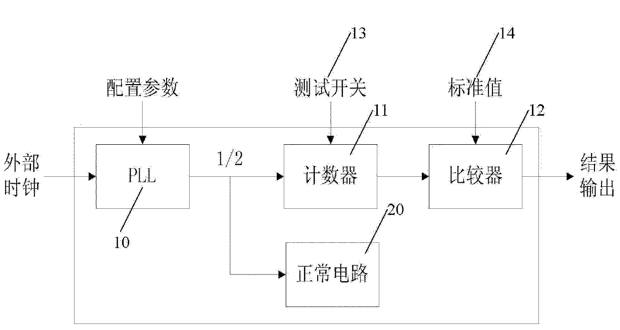
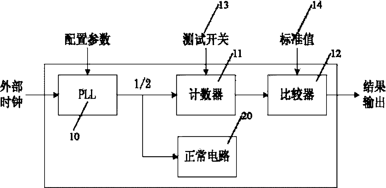
[0051] figure 1 A first preferred embodiment of the invention is shown.

[0052] Such as figure 1 As shown, the PLL 10 is the PLL circuit under test, and the input of the PLL circuit 10 is the external clock and the actual configuration parameters of the PLL circuit (the parameters are corresponding working parameters predetermined by the m...


PUM


Abstract

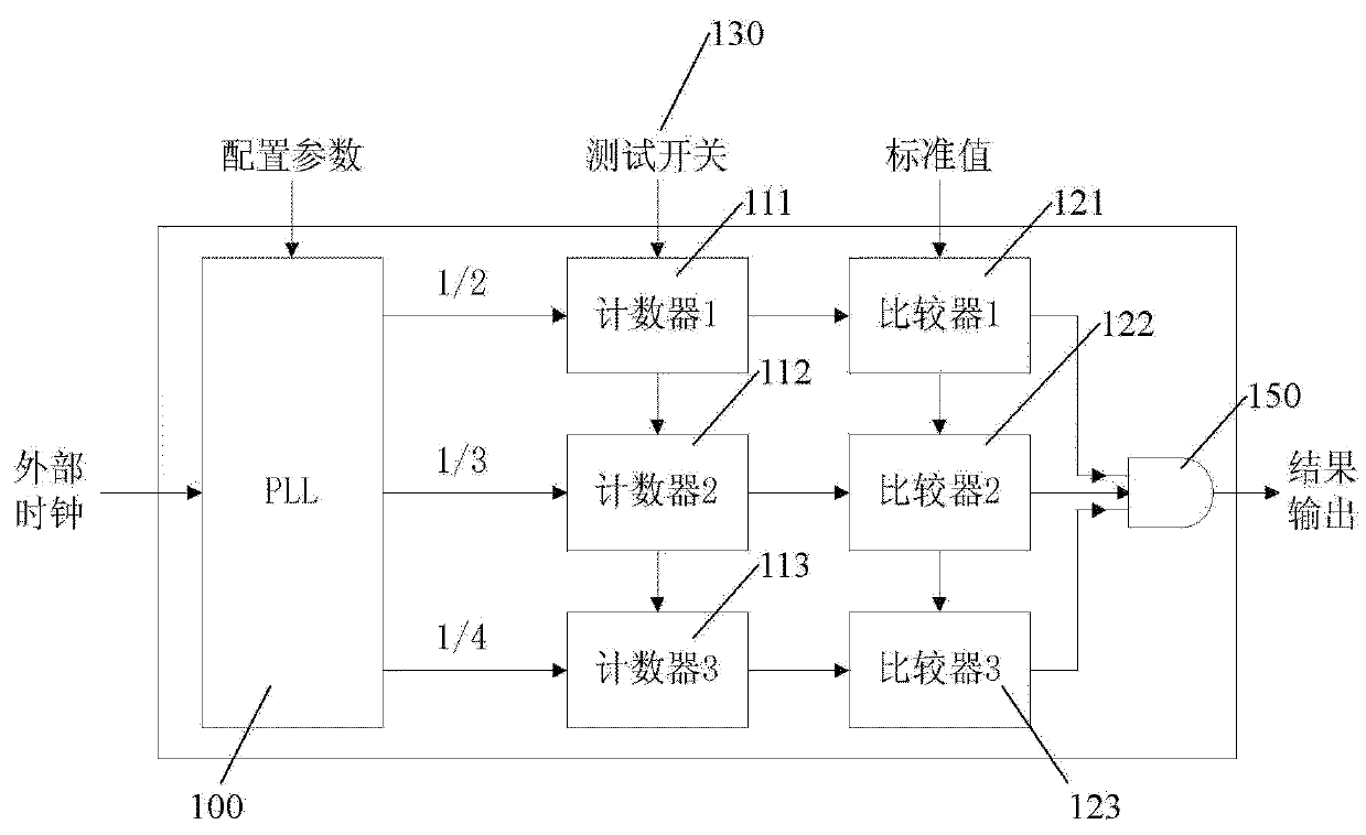
The invention discloses an ATE (Automatic Test Equipment) test circuit for PLL (Phase Locked Loop) and a test method thereof. The test circuit is arranged at the periphery of a tested PLL circuit, and comprises a test control circuit, a test switch, one or more counters, a comparator and a test result output circuit, wherein the comparator corresponds to each counter. The test method comprises the following steps of: (1) configuring PLL circuit parameters and the test control circuit; (2) starting the test switch; (3) counting by the counter; (4) closing the test switch; (5) comparing, by the comparator, an output value of the counter with a standard value; and (6) outputting the test result. The test circuit provided by the invention is organized in the form of module; the output of the test circuit can be effectively tested in a PLL operation process; the correctness of the PLL output can be judged; the test result is directly output at the end of test; the hardware expenditure is low; the control is simple; and the complexity and the operation difficulty of a test vector used by the ATE are greatly reduced.

Description

technical field [0001] The present invention relates to the field of automatic testing, in particular to the field of testing methodology for ATE (Automatic Test Equipment, i.e. automated testing equipment) testing machines, and more specifically to the field of PLL (Phase Locked Loop, i.e. phase locked loop) circuits Test circuits and test methods. Background technique [0002] With the rapid development of the integrated circuit industry, integrated circuit testing plays an increasingly important role in the industry chain, and specialized integrated circuit testing is an important part of the integrated circuit industry. In the current integrated circuit industry, due to the limitations of special testers, non-standardization and the long development cycle of special testers, the use of special testers has been greatly restricted. Its versatility, standardization, portability and openness have quickly become the mainstream of the integrated circuit testing industry. [...

Claims


Application Information

Patent Timeline
IPC IPC(8): H03L7/08H03L7/18
Inventor 毛鲁丁
Owner 北京国睿中数科技股份有限公司
Learn More