
Automatic remaining dynamic correction method

A dynamic correction and automatic technology, applied in the field of automatic residual dynamic correction based on cross-correlation, can solve the problems of complex pre-stack migration imaging processing process, little practical operation significance, large manual workload, etc. The effect of high calculation efficiency and simple calculation steps

Active Publication Date: 2014-09-10
BC P INC CHINA NAT PETROLEUM CORP +1
View PDF1 Cites 0 Cited by
  • Summary
  • Abstract
  • Description
  • Claims
  • Application Information

AI Technical Summary

Problems solved by technology

However, the research in this area mainly relies on the experience of interpreters to pick up and adjust the seismic velocity, which requires a lot of manual work, and different processing interpreters will get quite different seismic velocity fields based on their experience, so it is difficult to be accurate. Establishment and imaging of the subsurface velocity field
[0007] Although the anisotropic dynamic correction and high-order dynamic correction methods have the advantages of high precision, they are not suitable for imaging of complex structures. The pre-stack migration imaging process is complicated and the calculation period is long, so the actual operation is of little significance

Method used


Image

  • Automatic remaining dynamic correction method

Examples


Embodiment Construction

[0017] Embodiments of the invention will now be described in detail, examples of which are illustrated in the accompanying drawings, wherein like reference numerals refer to like parts throughout. The embodiments are described below in order to explain the present invention by referring to the figures.

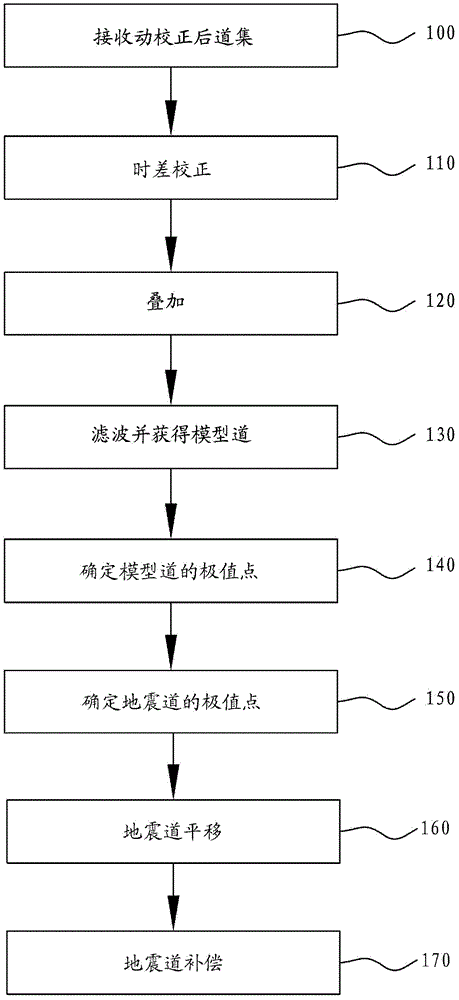
[0018] Below, combine figure 1 A cross-correlation-based efficient automatic residual motion correction method according to an exemplary embodiment of the present invention will be described in detail.

[0019] At step 100, a plurality of motion corrected gathers are received. As is known in the art, a gather includes multiple seismic traces. A seismic trace represents a series of sample point values ​​(sample point values ​​of seismic data), and each sample point value represents the amplitude (also called energy) at a certain time point of a time series.

[0020] In step 110, cross-correlation time difference correction is performed. As is well known in the art, performi...


PUM


Abstract

The invention provides an automatic remaining dynamic correction method. The method comprises the following steps of: performing cross-correlation time difference correction on a plurality of seismic channels of a channel set which is selected from a plurality of received channel sets which are dynamically corrected; overlapping the seismic channels which are subjected to time difference correction in the selected channel set to form a seismic channel datum; filtering the seismic channel datum which is obtained by overlapping to form a model channel of the selected channel set; determining an extreme point of the model channel; determining the extreme point, corresponding to the extreme point of the model channel, in the seismic channel which is selected from a plurality of seismic channels which are not subjected to time difference correction in the selected channel set; on the basis of time difference of the extreme point of the selected seismic channel and the extreme point of the model channel, translating the selected seismic channel, wherein the extreme point of the model channel corresponds to the extreme point of the selected seismic channel; and interpolating the translated seismic channel to finish automatic remaining dynamic correction of the selected seismic channel.

Description

technical field [0001] The invention relates to the field of geophysical exploration, in particular to an automatic residual motion correction method based on cross-correlation. Background technique [0002] Research on imaging methods in complex areas is a frontier research topic that has existed for a long time in petroleum geophysical exploration and has not yet been fully resolved. The current research has achieved many theoretical and practical results. However, most of the current research focuses on the following two aspects: [0003] (1) Study how to use anisotropic motion correction and high-order motion correction methods [0004] The main research includes two parts: one is to improve the calculation accuracy of the stacking velocity, the main method is to use the anisotropic velocity analysis to obtain the stacking velocity and anisotropy parameters, etc., so as to realize the correctness of the middle and far offset distances of the dynamic correction gathers ...

Claims


Application Information

Patent Timeline
Patent Type & Authority Patents(China)
IPC IPC(8): G01V1/36
Inventor 罗红明何光明陈爱萍曹中林张华刘鸿金德刚陈三平
Owner BC P INC CHINA NAT PETROLEUM CORP
Learn More