
Method for calibrating and correcting temperature measurement of infrared probe as well as corresponding temperature measuring method

A technology of infrared detector and calibration method, applied in radiation pyrometry, instruments, measuring devices, etc., can solve the problems of temperature measurement accuracy drop, temperature measurement error, deviation of calibration results, etc.

Active Publication Date: 2012-07-11
UNIV OF ELECTRONICS SCI & TECH OF CHINA
View PDF5 Cites 47 Cited by
  • Summary
  • Abstract
  • Description
  • Claims
  • Application Information

AI Technical Summary

Problems solved by technology

If the two steps are separated, it may appear that in the process of temperature measurement calibration, due to various reasons outside or inside the detector, new changes have taken place in the non-uniformity of the infrared focal plane, and the previous non-uniform correction parameters are no longer Applicable, the deviation of the calibration result will lead to a decrease in the accuracy of the calibration, which will eventually lead to a decrease in the accuracy of the temperature measurement
At present, there is no calibration-calibration method that combines the two methods, so the current methods may cause certain errors in temperature measurement after calibration and calibration.

Method used


Image

  • Method for calibrating and correcting temperature measurement of infrared probe as well as corresponding temperature measuring method
  • Method for calibrating and correcting temperature measurement of infrared probe as well as corresponding temperature measuring method
  • Method for calibrating and correcting temperature measurement of infrared probe as well as corresponding temperature measuring method

Examples


Embodiment Construction

[0036] The present invention will be further described below in conjunction with the accompanying drawings and specific embodiments.

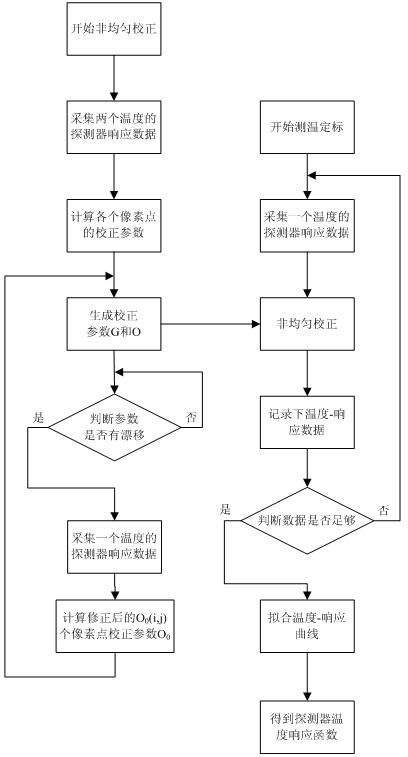
[0037] Such as figure 1 As shown: the process of temperature measurement calibration and non-uniform correction is that the non-uniform correction starts first, and after the calibration parameters G and O are generated, the temperature measurement calibration starts. If there is a drift, correct the parameters if there is a drift, otherwise continue to judge.

[0038] The process of temperature measurement calibration is to collect the detector response of each temperature, perform a non-uniform correction on it using the previously calculated non-uniform parameters, and then record the temperature and detector response data. Repeat this process until enough data is collected, and then fit the data to obtain the detector temperature response function.

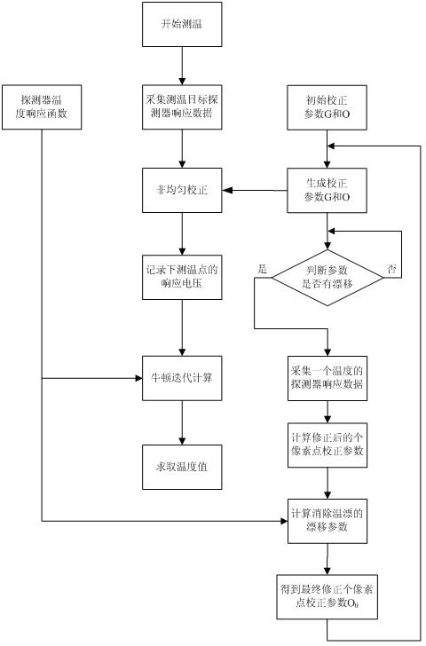
[0039] Such as figure 2 Shown: The previous non-uniform correction parameters and detec...


PUM


Abstract

The invention discloses a method for calibrating and correcting temperature measurement of an infrared probe as well as a corresponding temperature measuring method. The temperature measurement calibration and non-uniform correction process is as follows: the non-uniform correction is carried out firstly; the temperature measurement calibration is carried out after a collection parameter sum is generated; however, the non-uniform correction is not stopped simultaneously; and in the non-uniform correction, a step of circularly judging whether an extrusion exists in a parameter or not is carried out; and if so, the parameter is corrected; otherwise, the judgment is continuously carried out. A temperature measurement calibrating process comprises the following steps of: carrying out the non-uniform correction once by using the calculated non-uniform parameter for each probe response of collecting a temperature; then recording the temperature and probe response data; repeating the processuntil collecting enough data; and fitting the data to obtain a probe temperature response function. By utilizing the method disclosed by the invention, the steps of non-uniformly correcting and calibrating the temperature measurement of the infrared probe are simplified into one step, so that the correction and the calibration which can be previously realized by the two steps are conveniently realized on one hand, and the precision of the temperature measurement can be improved on the other hand.

Description

technical field [0001] The invention relates to the field of uncooled infrared detectors, in particular to a calibration and calibration method of the uncooled infrared detector and a corresponding temperature measurement method. Background technique [0002] Uncooled infrared focal plane arrays were developed in the late 1970s and early 1980s, driven by defense applications and other strategic and tactical applications. It is an important optoelectronic device to obtain the infrared thermal radiation information of the scene. In addition to being used in traditional situational imaging, it is also widely used in industrial automation, medical diagnosis, chemical process detection, infrared astronomy and other fields. [0003] The infrared detector made of uncooled infrared focal plane array can perform infrared temperature measurement, which belongs to a kind of non-contact temperature measurement. It measures the temperature of the measured object by measuring the infrare...

Claims


Application Information

Patent Timeline
IPC IPC(8): G01J5/00
Inventor 刘子骥曾星鑫蔡贝贝杨书兵郑兴
Owner UNIV OF ELECTRONICS SCI & TECH OF CHINA
Learn More