
Multimedia intelligent sensor network system and method based on controller area network (CAN) bus

A CAN bus, intelligent sensor technology, applied in the field of multimedia intelligent sensor network system, can solve the problems such as the inability to fully exert the advantages of Ethernet network speed, the inability to guarantee the real-time requirements of data transmission, and the inconvenience of node access to the network, etc. High reliability and safety, saving installation costs, and convenient and simple wiring

Active Publication Date: 2015-01-14
ZHEJIANG UNIV
View PDF2 Cites 0 Cited by
  • Summary
  • Abstract
  • Description
  • Claims
  • Application Information

AI Technical Summary

Problems solved by technology

However, to establish a sensor network with many nodes using Ethernet, the CSMA / CD protocol of Ethernet cannot guarantee the real-time requirements of data transmission. It adopts a timeout retransmission mechanism, and single-point faults are easy to spread, causing the paralysis of the entire sensor network system. Poor adaptability to some harsh industrial environments
In addition, for some scenarios where sensor nodes are widely distributed and scattered, the cost of deploying Ethernet is relatively high, and it is inconvenient for nodes to access the network
For some occasions that do not need to continuously and frequently collect video data and transmit a large amount of data, the network speed advantage of Ethernet cannot be fully utilized

Method used


Image

  • Multimedia intelligent sensor network system and method based on controller area network (CAN) bus
  • Multimedia intelligent sensor network system and method based on controller area network (CAN) bus
  • Multimedia intelligent sensor network system and method based on controller area network (CAN) bus

Examples


Embodiment

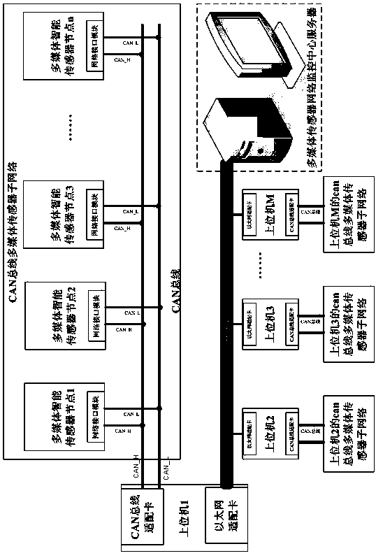
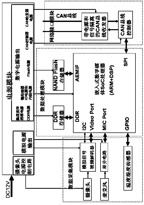
[0077]The present invention adopts the embedded microprocessor as the core to collect, process and analyze the multimedia intelligent sensor of audio and video and temperature and humidity to form the system of the sensor network. The sensor node circuit, and the collection and analysis of field data in the CAN bus network system are completed by intelligent sensors. Figure 1 is a CAN bus multimedia intelligent sensor network topology diagram, which is mainly composed of a monitoring center server, a PC host computer and various nodes. The PC host computer and the nodes on its sub-network are connected by the CAN bus, and each PC host computer is connected to an Ethernet network. The way and the server of the monitoring center form the whole multimedia intelligent sensor network. A single node is composed of a power supply module, a data acquisition module, a data processing module and a network interface module, and is connected to the CAN bus through the CAN control and the ...


PUM


Abstract

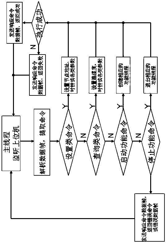
The invention relates to a multimedia intelligent sensor network system and a method based on a controller area network (CAN) bus. A multimedia sensor in a network has the action on monitoring audio and video, collecting temperature and humidity and intelligently analyzing data. The network node of the intelligent sensor and an upper computer are connected into a subnetwork system by the CAN bus; further, each upper computer and the server of a monitoring center are networked in an Ethernet mode to form an integral intelligent network system; and the requirements of wide and dispersive node distribution, distributed acquisition and real-time monitoring can be effectively satisfied. Each intelligent node comprises a power supply module, a data acquisition module, a data processing module and a network interface module. An implementation method is characterized in that the functions of setting and inquiring status parameters, monitoring the temperature and the humidity, collecting, coding and transmitting the audio and the video and intelligently analyzing the video according to the communication protocol and the relevant flow are realized according to the data communication protocol and the relevant flow. The multimedia intelligent sensor network with complete function and low cost is built by the small and efficient intelligent node with low cost and low energy consumption.

Description

technical field [0001] The invention relates to a multimedia intelligent sensor network system, in particular to a CAN bus-based multimedia intelligent sensor network system and method. Background technique [0002] The development of network technology has made remote monitoring and data collection popular. The smart sensor usually takes the microprocessor as the core, and can detect the input signal through the sensor, judge and make decisions according to the value of the input signal; set and realize different functions through software control; and communicate with the host through the standard input and output interface. machine for information exchange. The intelligent sensor network makes the sensor develop from single function and single detection to multi-function and multi-point detection; from passive detection to active information processing; from local measurement to remote real-time online measurement and control. Networking enables sensors to be connected ...

Claims


Application Information

Patent Timeline
Patent Type & Authority Patents(China)
IPC IPC(8): H04L12/40H04L29/06
Inventor 于慧敏杨辉
Owner ZHEJIANG UNIV
Learn More