
Multi-way asymmetrical Doherty amplifier

An amplifier, asymmetric technology, applied in the direction of amplifiers, improving amplifiers to improve efficiency, amplifying components of devices, etc., to achieve the effects of good linearity, high efficiency, peak-to-average ratio and efficiency requirements

Inactive Publication Date: 2012-07-04
WUHAN GEWEI ELECTRONICS TECH
View PDF7 Cites 26 Cited by
  • Summary
  • Abstract
  • Description
  • Claims
  • Application Information

AI Technical Summary

Problems solved by technology

[0004] At present, the traditional Doherty amplifier circuit can achieve the best efficiency of about 50% when the signal peak-to-average ratio is 5-7dB. After being applied to the RF power amplifier, the highest efficiency can only reach about 43%, which is very It is difficult to further improve, but with the further development of wireless broadband networks, the bandwidth of the signal is required to be wider and wider, the peak-to-average ratio of the signal is also higher and higher, and the efficiency of the power amplifier is required to be higher and higher

Method used


Image

  • Multi-way asymmetrical Doherty amplifier
  • Multi-way asymmetrical Doherty amplifier
  • Multi-way asymmetrical Doherty amplifier

Examples


Embodiment 1

[0024] figure 2 It is a schematic circuit diagram of an embodiment of the present invention, which includes a multi-channel power distribution network circuit, a carrier amplifier C1, at least 2 peak amplifiers P1-Pn, and an output power synthesis and impedance transformation network circuit; a carrier amplifier and a peak amplifier The input terminals of the carrier amplifier and the peak amplifier are connected to the output power combining and impedance transformation network circuit respectively.

[0025] Among the at least two peak amplifiers, the power of the first peak amplifier is 0.7 to 1.3 times the power of the carrier amplifier, and the power of the remaining peak amplifiers is doubled step by step, and the doubling factor is 1.5 to 2.5, defined as The power of the carrier amplifier is P c , the power of the peaking amplifier is staged as P p1 ,P p2 ...P p(n-1) ,P pn , then P p1 =(0.7~1.3)P c ,P p2 =(1.5~2.5)P p1 ,...,P pn =(1.5~2.5)P p(n-1) , where n i...

Embodiment 2

[0047] This example Figure 4 As shown, the structure and principle are basically the same as those in Embodiment 1, the difference is that a delay phase-shift amplitude modulation network circuit is connected in series before each carrier amplifier and peak amplifier, which is used to introduce group delay, insert phase and insert Loss, so that the group delay, insertion phase, and gain parameter characteristics of the amplification path in the working frequency band are consistent. The time-delay phase-shift amplitude modulation network circuit includes at least one element among microstrip line, strip line, surface mount element and coaxial cable.

[0048] Delay, phase shift and amplitude modulation network circuit introduces parameter characteristics such as delay, insertion phase, insertion loss or gain, and works in combination with the carrier amplifier and peak amplifier, and then cooperates with the power distribution network circuit, power synthesis and impedance cha...


PUM


Abstract

The invention provides a multi-way asymmetrical Doherty amplifier, which comprises a multi-way power splitting network circuit, a carrier amplifier, at least two peak amplifiers and an output power combination and impedance conversion network circuit. An input end of the carrier amplifier and input ends of the peak amplifiers are respectively connected with the multi-way power splitting network circuit, and an output end of the carrier amplifier and output ends of the peak amplifiers are respectively connected with the output power combination and impedance conversion network circuit. In the peak amplifiers, the power of the first peak amplifier is 0.7-1.3 times of that of the carrier amplifier, and the power of the other peak amplifiers is doubled gradually with the doubling coefficient ranging from 1.5 to 2.5. When GSM (global system for mobile communication) multi-carrier signals with the peak-to-mean ratio of 7dB are output while the circuit of a three-way asymmetrical Doherty amplifier returns by 7dB, the efficiency can be over 56%, and higher peak-to-mean ratio and efficiency requirements can be met along with increase of the stage number of the peak amplifiers.

Description

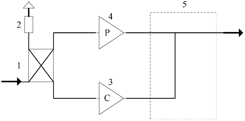
technical field [0001] The invention belongs to the technical field of base station power amplifiers, and in particular relates to a multi-channel asymmetrical Doherty amplifier structure used in a multi-carrier base station system. Background technique [0002] The RF power amplifier is a key component of the wireless communication base station system. Most of the energy consumption of the base station system is consumed by the RF power amplifier. With the emphasis on environmental protection, the wireless communication field has higher and higher requirements for the efficiency of the RF power amplifier. [0003] The Doherty amplifier is the most widely used high-efficiency technology in the current wireless communication system. The principle of the traditional Doherty amplifier circuit is as follows: figure 1 As shown, it is composed of an input power splitter 1, a carrier amplifier 3, a peak amplifier 4, and a power combining / impedance transformation network circuit 5, ...

Claims


Application Information

Patent Timeline
Patent Type & Authority Applications(China)
IPC IPC(8): H03F1/07
CPCH03F2200/405H03F1/07H03F1/0288
Inventor 孟庆南
Owner WUHAN GEWEI ELECTRONICS TECH
Learn More