
Electric motor and vehicle drive device using the same

A technology of electric motors and assemblies, which is applied in the field of vehicle drive devices and electric motors, and can solve problems such as temperature rise

Inactive Publication Date: 2016-03-30
AISIN SEIKI KK
View PDF3 Cites 0 Cited by
  • Summary
  • Abstract
  • Description
  • Claims
  • Application Information

AI Technical Summary

Problems solved by technology

In such a rotating electrical machine, there is a disadvantage in that the temperature rises due to the need for a large current to flow during use, or because it is used near an engine, etc.

Method used


Image

  • Electric motor and vehicle drive device using the same
  • Electric motor and vehicle drive device using the same
  • Electric motor and vehicle drive device using the same

Examples


Embodiment Construction

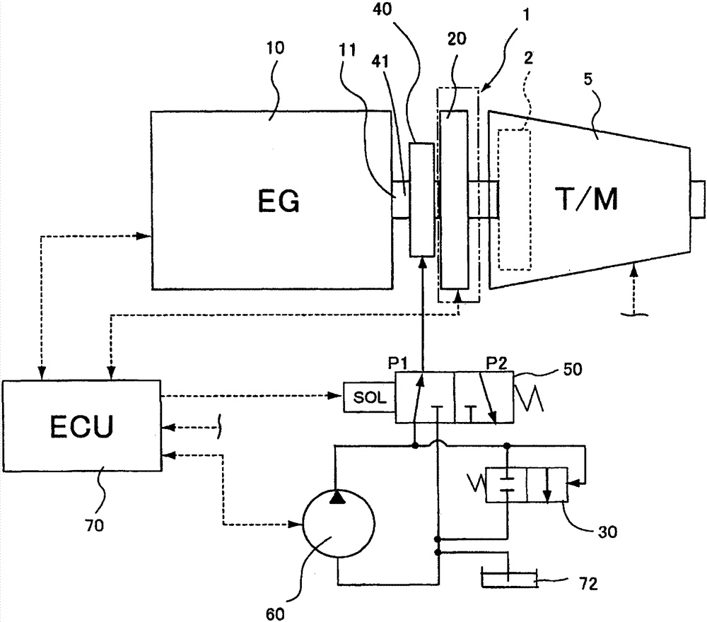
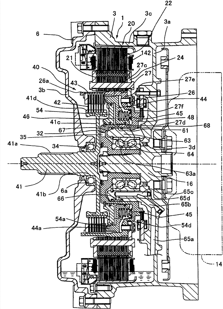
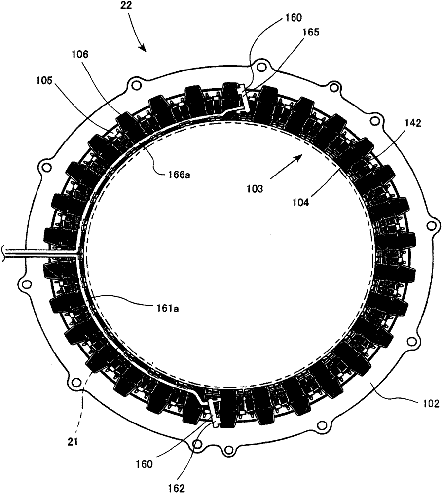
[0042] Hereinafter, embodiments according to the present invention will be described with reference to the drawings embodied as a hybrid vehicle. figure 1 A schematic diagram showing a hybrid vehicle drive system using the electric motor 20 according to the present invention and the vehicle drive device 1 using the electric motor 20 . In addition, if figure 2 As shown, the drive device 1 for a vehicle is composed of a casing 3, an output shaft 26, and an electric motor 20, wherein the output shaft 26 is pivotally supported on the casing 3 so as to be rotatable around a rotation axis, and the electric motor 20 has a rotor 21 integrally rotating Combined with the output shaft 26 , the stator 22 opposite to the rotor 21 is fixed on the housing 3 .

[0043] exist figure 1 In , the arrows of the solid line indicate the hydraulic piping connecting each device, and the arrows of the broken line indicate the signal lines for control. In addition, in figure 1 In the figure, the el...


PUM


Abstract

An electric motor and a vehicle drive device having the same are provided. The electric motor includes a core unit having plural core assemblies fixed to a case, an annular bus ring attached to the core unit, plural supporting members attached the plural core assemblies, respectively, an attachment member holding a first sensor and fixed to a portion of a terminal accommodating portion such that the first sensor is soaked in an oil stored in the case, and an attachment member holding a second sensor and fixed to a portion of a terminal accommodating portion such that the second sensor is positioned at a second position for measuring a temperature of the coils between adjacent terminal accommodating portions which are not soaked in the oil.

Description

technical field [0001] The present invention relates to an electric motor and a vehicle drive device using the electric motor as a drive source. Background technique [0002] Currently, rotating electrical machines such as electric motors and generators are incorporated into driving devices of hybrid vehicles and electric vehicles. In such a rotating electrical machine, there is a disadvantage in that the temperature rises due to the need for a large current to flow during use, or because it is used near an engine. Therefore, it is important to simultaneously monitor the temperature of the coil and the oil temperature of lubricating and cooling oil with a temperature sensor, and to ensure safety by performing appropriate control such as operating a safety circuit when the temperature rises. [0003] For example, in the technique disclosed in Patent Document 1, a thermistor 50 serving as a temperature sensor is inserted into a temperature detection insertion hole 17 wound in...

Claims


Application Information

Patent Timeline
Patent Type & Authority Patents(China)
IPC IPC(8): H02K11/25B60K6/26
CPCB60L3/0061B60L15/2054B60L50/16B60L2210/40B60L2220/14B60L2220/50B60L2240/12B60L2240/36B60L2240/421B60L2240/423B60L2240/425B60L2240/441B60L2240/443B60L2250/24B60L2270/145H02K3/522H02K7/006H02K11/25H02K2203/09Y02T10/64Y02T10/7072Y02T10/72Y10T74/19051Y02T10/70
Inventor 前川悠生永田裕之
Owner AISIN SEIKI KK
Learn More