
Composite material light energy-saving conductor spacer

A composite material and fiber composite material technology, which is applied in the field of composite material lightweight energy-saving spacer bars, can solve the problems of poor self-adhesion and mutual adhesion, difficult production of non-magnetic steel, and has not been widely promoted, and achieves mechanical strength. Large, extensive market competitiveness, long anti-aging effect

Inactive Publication Date: 2012-07-04
WUHAN NARI LIABILITY OF STATE GRID ELECTRIC POWER RES INST +1
View PDF4 Cites 10 Cited by
  • Summary
  • Abstract
  • Description
  • Claims
  • Application Information

AI Technical Summary

Problems solved by technology

There are two problems in this method: first, polyamide is more expensive and difficult to promote, and this material can be recycled, but in view of the special geographical environment where electric power fittings are located, the recyclable amount is small and difficult to recycle Second, the non-magnetic steel used in this electric power fitting is difficult to produce and has not been widely promoted
The Chinese patent publication number is CN1560876A, and the invention patent named "Ultra-high voltage transmission line spacer rubber damping part" uses EPDM rubber to replace iron components. Ethylene propylene rubber has low cohesive energy due to the lack of active groups in its molecular structure. In addition, the rubber material is easy to bloom, and the self-adhesiveness and mutual adhesion are very poor. After treatment, the vulcanization speed and adhesive performance of ethylene-propylene rubber can be improved, but the mechanical strength is reduced.
Existing materials only solve part of the problem, only belong to the experimental stage, and have no practical application

Method used


Image

  • Composite material light energy-saving conductor spacer
  • Composite material light energy-saving conductor spacer
  • Composite material light energy-saving conductor spacer

Examples


Embodiment Construction

[0038] The present invention will be further described below in conjunction with the accompanying drawings.

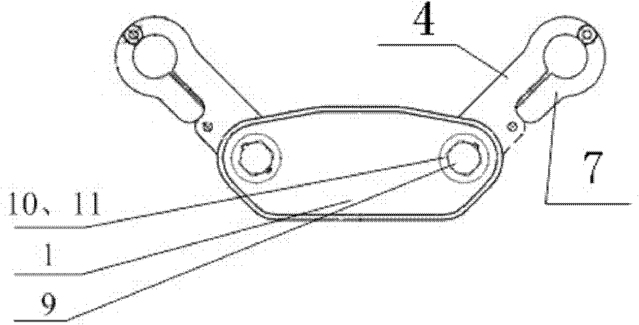
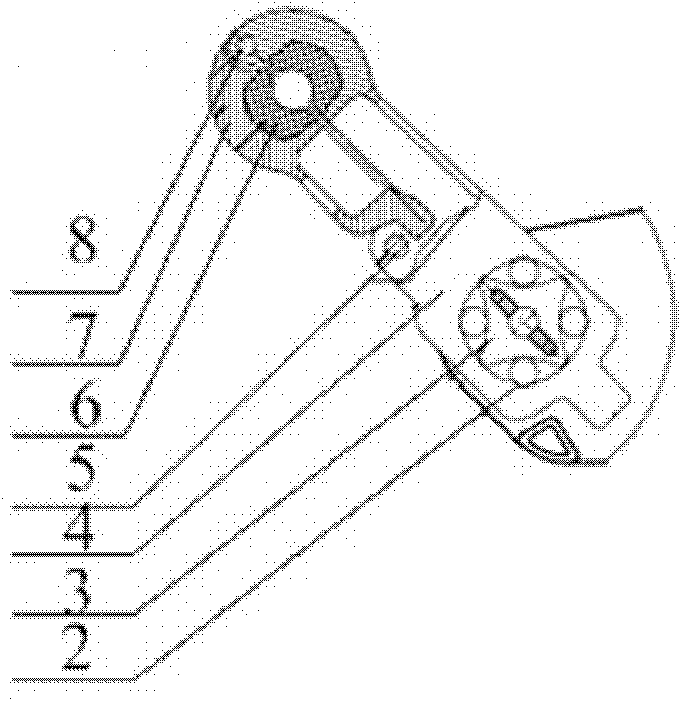
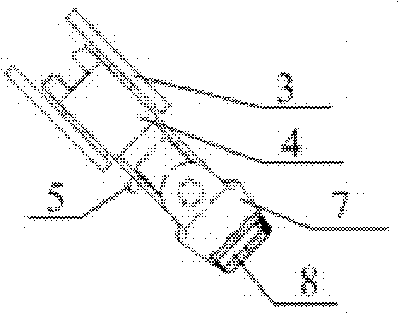
[0039] as attached Figures 1 to 6 As shown, a lightweight energy-saving spacer made of composite material is composed of a frame 1, a rubber column 2, a cross sleeve 3, a clamp body 4, a lock pin 5, a rubber pad 6, a cover plate 7, a hinge pin 8, and a bolt 9. Composed of nut 10 and washer 11, the clamp body 4 is connected to the frame 1 through the rubber column 2, the cross sleeve 3, the nut 10, the washer 11, and the bolt 9, and one end of the cover plate 7 is connected to the clamp body through the lock pin 5 4 connection, the other end of the cover plate 7 is connected with the clamp body 4 through the hinge pin 8, the clamp body 4 and the cover plate 7 form a groove for containing the wire, and rubber pads 6 are arranged around the edge of the groove, so The frame 1, the cross sleeve 3, the clamp body 4, and the cover plate 7 are made of fiber composite materia...


PUM

PropertyMeasurementUnit
tensile strengthaaaaaaaaaa
hardnessaaaaaaaaaa
elongationaaaaaaaaaa

Abstract

The invention discloses a composite material combination type light energy-saving conductor spacer, which is formed in the way that a frame (1), a cross shaft sleeve (3), a wire clip body (4) and a cover plate (7) are all made of fiber composite materials on the basis of a common conductor spacer. The conductor spacer adopts the fiber composite materials and a specially optimized structure, does not generate hysteresis lag or eddy-current loss, does not generate corona, is free of corona noise and electromagnetic energy loss, and is obvious in energy saving effects. The conductor spacer is high in mechanical strength, stable in grip power, waving resistant and small in maintenance cost. By means of special optimized structure design, the conductor spacer effectively prevents abrasion caused of connection of different materials of connection joints, improves abrasion resistance, prolongs service life, is light in weight and convenient to construct and install, saves electric energy and is remarkable in economical and social benefits.

Description

technical field [0001] The invention relates to a spacer bar, in particular to a lightweight energy-saving spacer bar made of composite material. Background technique [0002] In overhead power transmission and transformation lines, traditional cast iron spacers cannot solve the problems of bulkiness, large hysteresis and eddy current loss, corona and noise. In order to solve the above problems, the development demand for a new generation of lightweight energy-saving spacers is becoming more and more Urgent, and there are many new technologies and new products. Among them, a number of related Chinese invention patents and utility model patents for spacers have been disclosed. Their structural materials are different, and to a certain extent, they achieve the purpose of energy saving and circuit protection. The Chinese Patent Publication No. is CN101447657A, and the invention patent titled "Polymer Alloy Buffer Type Lightweight Spacer" discloses a spacer formed by precision...

Claims


Application Information

Patent Timeline
Patent Type & Authority Applications(China)
IPC IPC(8): H02G7/12
Inventor 陈勇覃兆宇柯磊吴仲岿王恩久黄亨
Owner WUHAN NARI LIABILITY OF STATE GRID ELECTRIC POWER RES INST
Learn More