Dual-fuel swirling atomizing nozzle for chemical regenerative cycle

A swirl atomizing nozzle and chemical regenerative cycle technology, applied in the combustion chamber, combustion method, combustion equipment and other directions, can solve the uneven mixing of cracked gas and air in the head, the atomization effect is not ideal, and the combustion effect is affected. and other problems, to achieve the effect of compact head structure, improved adaptability and economy, and easy layout and installation

Inactive Publication Date: 2014-06-11
HARBIN ENG UNIV
View PDF9 Cites 0 Cited by
  • Summary
  • Abstract
  • Description
  • Claims
  • Application Information

AI Technical Summary

Problems solved by technology

[0003] The traditional dual-fuel nozzle has the following defects: If the traditional gas path design adopts the design of the central nozzle injection, due to the large amount of gas with medium and low calorific value, the mixing of cracked gas and air at the head is uneven, the flame is elongated, and the high temperature area Later, even after adding swirl blades, the mixing situation has not changed very well, so a new mixing method is needed to improve the combustion of cracked gas fuel; for liquid fuel, the traditional atomization effect is still not good. Ideal, and its uneven distribution affects the combustion effect
[0005] In patents US2006080966A1, US5826423A, and US6655145B2, the dual-fuel nozzles involved use the openings on the vanes to enhance the mixing of gaseous fuel and airflow or the atomization of liquid fuel. However, these published patent documents all focus on one aspect , in the chemical reheating cycle, the fuel in both states needs to be considered, and in different working conditions, it is necessary to accurately grasp the proportion of each component

Method used


Image

  • Dual-fuel swirling atomizing nozzle for chemical regenerative cycle
  • Dual-fuel swirling atomizing nozzle for chemical regenerative cycle
  • Dual-fuel swirling atomizing nozzle for chemical regenerative cycle

Examples


Embodiment Construction

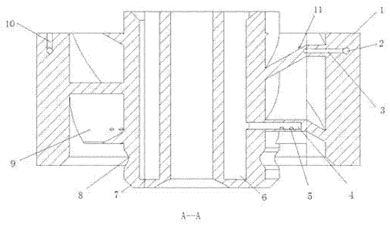
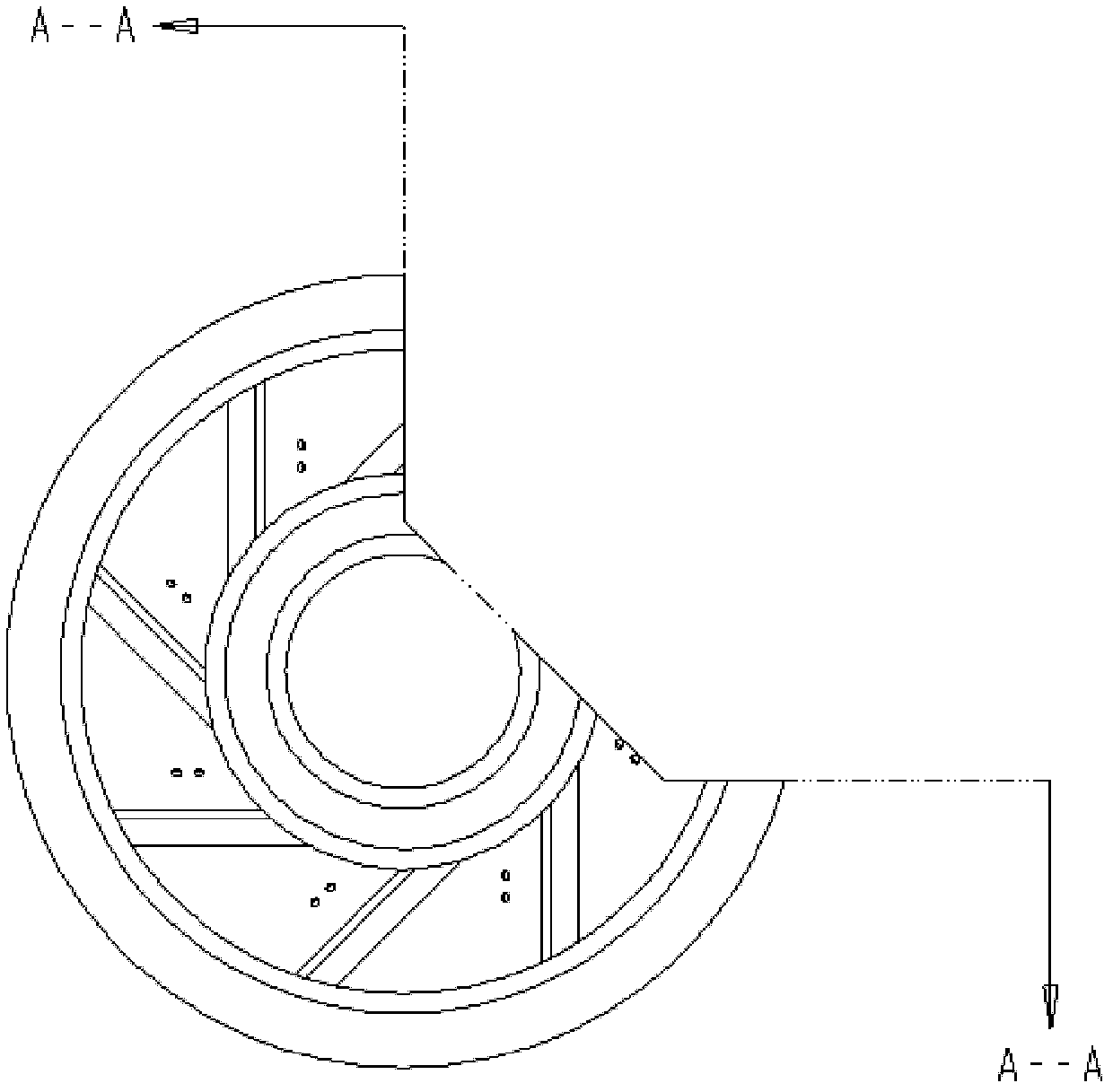
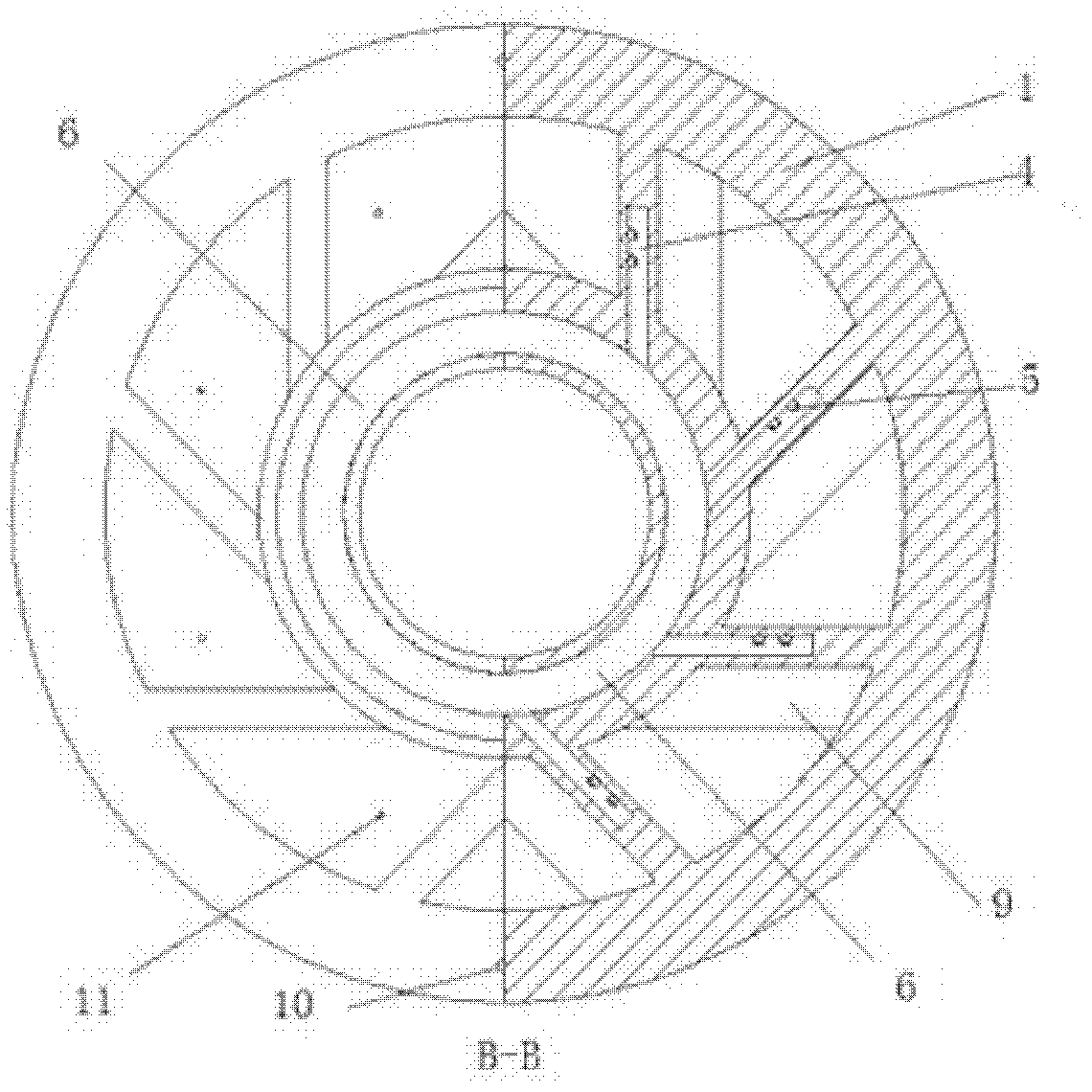
[0022] The present invention is described in more detail below in conjunction with accompanying drawing example:

[0023] combine Figure 1~5 , when injecting liquid fuel, the liquid fuel is directly injected into the high-speed airflow channel of the swirler, and when the high-speed airflow flows through the horizontally injected liquid column, the pressure on the windward side is higher and the pressure on the leeward side is lower, resulting in The aerodynamic force can squeeze the liquid column, and the liquid column is gradually flattened. Surface fluctuations appear on the windward and leeward sides of the fuel jet. The appearance of these fluctuations intensifies the bending of the jet, and the surface fluctuation increases along the direction of the jet. The jet breaks at the trough of the wave, and the broken fuel jet forms shorter fuel fragments, which are further broken into small particles. The diameter of the droplets produced by surface atomization is better tha...


PUM


Abstract

The invention aims to provide a dual-fuel swirling atomizing nozzle for chemical regenerative cycle, which comprises an outer swirler hub, a main oil way, a main cracked gas channel and swirler blades. An oil inlet is arranged on the outer swirler hub and communicated with the main oil way, the main oil way is communicated with oil spraying pores on windward sides of the swirler blades through branch channels of the oil way, and the main cracked gas channel is communicated with cracked gas nozzles on lee sides of the swirler blades through branch cracked gas channels. By the aid of the dual-fuel swirling atomizing nozzle, cracked gas fuels and air can be effectively mixed, flame is further shortened, and combustion efficiency and the integral performance of a gas turbine are improved. A swirler is combined with the nozzle, so that the head structure of a combustion chamber is more compact, and arrangement and installation of the combustion chamber are facilitated. Liquid fuels and the cracked gas fuels are independently supplied, so that the proportion of input fuels under various working conditions can be precisely controlled and mastered, and adaptability and economy of a combustion engine under the various working conditions are improved.

Description

technical field [0001] The invention relates to a nozzle in the industrial field. Background technique [0002] With the advancement of technology, people's requirements for the performance of gas turbines are also getting higher and higher. In order to improve the performance of gas turbines, many advanced cycle methods have been continuously proposed, and the chemical regenerative cycle is an advanced cycle method. Its main principle is as follows: the gas turbine chemical reheating cycle uses the exhaust gas of the gas turbine turbine as the heat source, and generates a new synthetic fuel, namely cracked gas fuel, through the steam reforming reaction of the fuel and water vapor. The fuel enters the combustor for combustion, thereby recovering waste heat in the exhaust gas of the turbine to improve thermal efficiency. Since the working method of the chemical regenerative cycle gas turbine (CRGT) determines that its combustion chamber adopts a dual-fuel system, it can be ...

Claims


Application Information

Patent Timeline
Patent Type & Authority Patents(China)
IPC IPC(8): F23R3/30F23R3/36F23R3/38
Inventor 康振亚李智明杨洪磊杨仁郑洪涛杨家龙张智博刘倩潘福敏
Owner HARBIN ENG UNIV
Why Eureka
Try Eureka