Composite atomizer for manufacturing gas atomization quick-coagulation spherical superfine metal powder

A technology for manufacturing gas and metal powder, applied in the field of metal powder manufacturing, can solve the problems of complex atomization equipment and achieve better atomization effect

Inactive Publication Date: 2011-02-09
HENAN POLYTECHNIC UNIV
View PDF7 Cites 8 Cited by
  • Summary
  • Abstract
  • Description
  • Claims
  • Application Information

AI Technical Summary

Problems solved by technology

This method has significantly improved the atomization effect, but the obtained powder is not spherical but in the shape of teardrops, and the atomization equipment is relatively complicated

Method used


Image

  • Composite atomizer for manufacturing gas atomization quick-coagulation spherical superfine metal powder
  • Composite atomizer for manufacturing gas atomization quick-coagulation spherical superfine metal powder
  • Composite atomizer for manufacturing gas atomization quick-coagulation spherical superfine metal powder

Examples


Embodiment 1

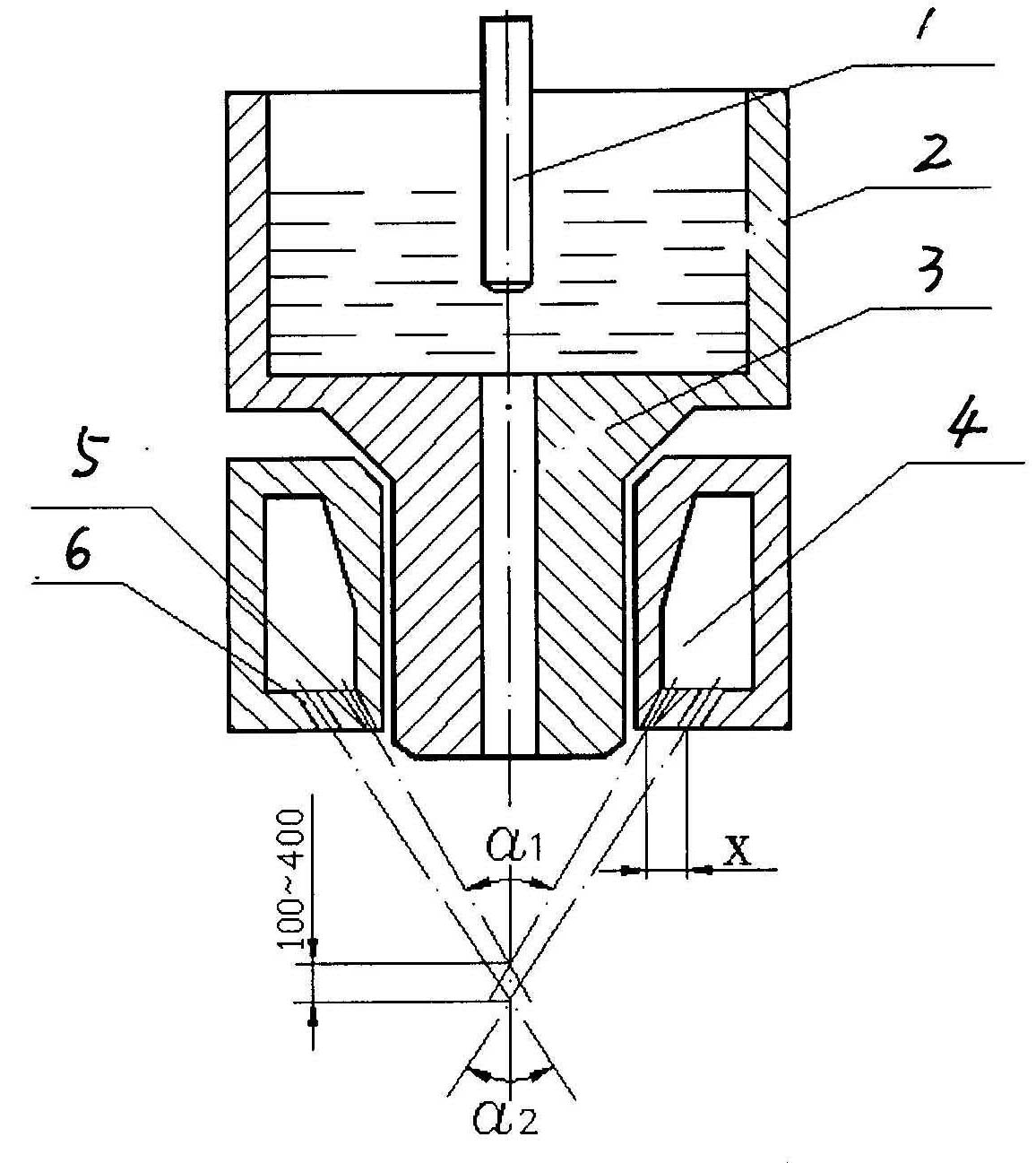
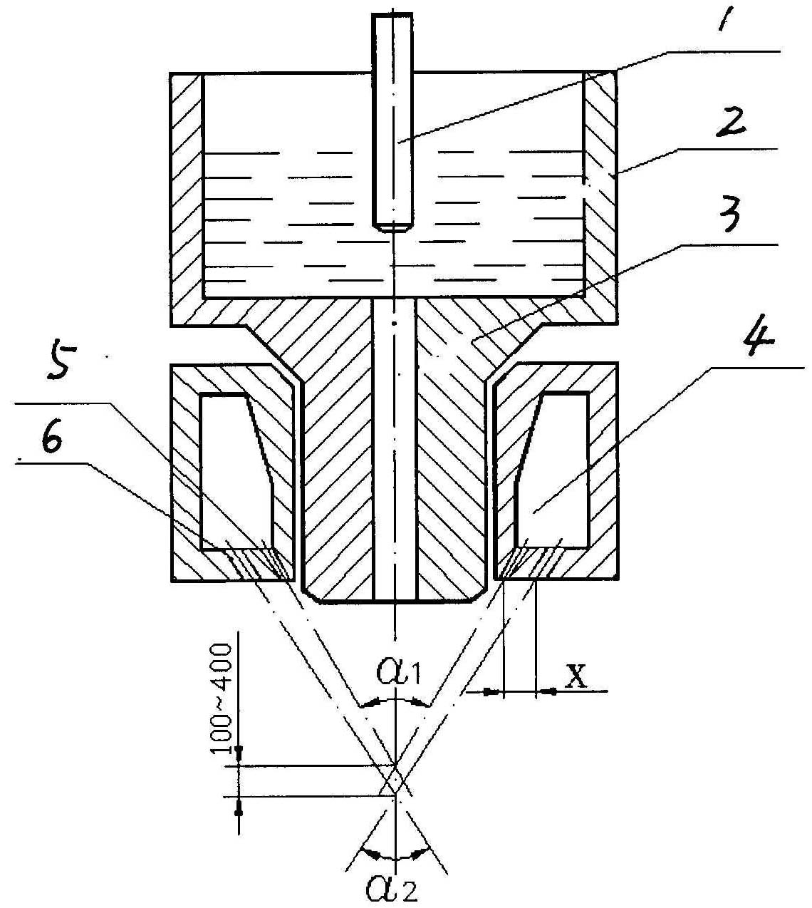
[0016] Such as figure 1 As shown, the composite atomizer for producing gas atomized and rapidly solidified spherical fine metal powder in this embodiment includes a clamp pot 2 for containing molten metal, and a metal liquid conduit 3 arranged around the bottom of the clamp pot is connected to a high-speed gas flow source An atomizer chamber 4 with an annular single-chamber structure in a continuous ring structure; surrounding the annular bottom surface of the atomizer chamber, there are two concentric circle structures formed by a number of nozzles arranged in an evenly distributed manner. The nozzle rings 5, 6 of the nozzles are all arranged in a sideways manner in which their axes intersect with the lower extension line of the catheter axis; wherein, the axes of all the nozzles on the inner nozzle ring 5 close to the catheter axis are the same Intersect with the catheter axis at the α1 vertex of the atomization zone II, and the axes of all nozzles on the outer nozzle ring 6...

Embodiment 2

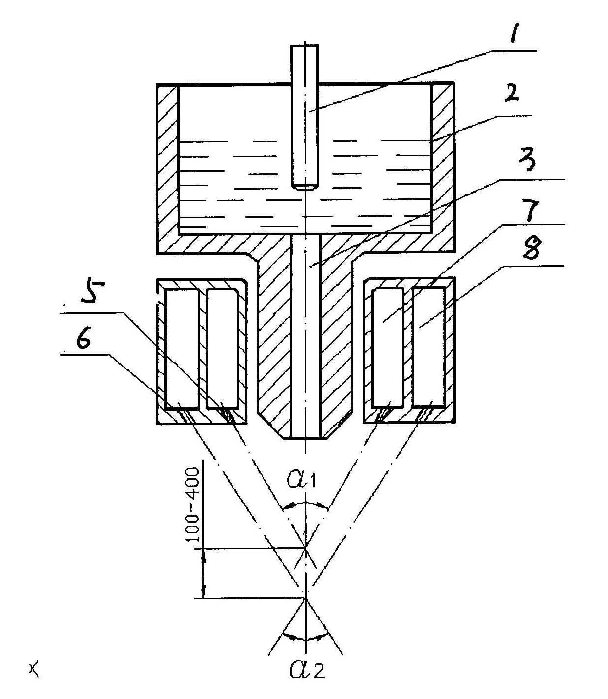
[0018] Such as figure 2 As shown, the difference between this embodiment and Embodiment 1 is that the atomizer chamber is an inner and outer ring cavity structure separated by a vertically arranged annular partition, and the nozzles arranged on the inner nozzle ring 5 All communicate with the inner ring chamber 7 , and the nozzles arranged on the outer nozzle ring 6 communicate with the outer ring chamber 8 .

[0019] When the composite atomizer of the present invention is used for the manufacture of amorphous Al-Ni-Y alloy spherical powder, the gas atomization pressure is 1.0Mpa, and the cooling rate reaches 10 6 K / s, the average particle size of the prepared Al-Ni-Y amorphous powder is 7-12 μm.

[0020] When the composite atomizer of the present invention is used in the manufacture of Al-Mn quasi-crystal spherical powder, the atomization pressure is 1.5 Mpa, and the average particle size of the prepared Al-Mn quasi-crystal powder is 10-14 μm.

[0021] When the compound a...


PUM


Abstract

The invention relates to a composite atomizer for manufacturing gas atomization quick-coagulation spherical superfine metal powder, which comprises a crucible for containing metal liquid and an atomizer stationing chamber which is arranged around a metal liquid guiding pipe at the bottom of the crucible, is communicated with a high-speed airflow source and has an annular structure. The composite atomizer is characterized in that: inner and outer nozzle rings which are formed by a plurality of nozzles arranged in a mode of uniform distribution and have structures of concentric circles are formed around the annular bottom surface of the atomizer stationing chamber, and the nozzles are arranged in a skew mode which makes the axes of the nozzles intersected with the lower extended line of the axis of the liquid guiding pipe, wherein the axes of all nozzles on the inner nozzle rings close to the axis of the liquid guiding pipe and the axis of the liquid guiding pipe intersect at a vertical angle point alpha 1 in an atomizing area II, the axes of all nozzles on the outer nozzle rings away from the axis of the liquid guiding pipe and the axis of the liquid guiding pipe intersect at a vertical angle point alpha 2 of an atomizing area III, and the distance between the two vertical angle points is between 0.1 and 0.4 millimeter; and the atomizing pressure is controlled to be between 0.5 and 2.5 MPa.

Description

technical field [0001] The invention belongs to the field of metal powder manufacture, and in particular relates to a composite atomizer for manufacturing gas atomized rapidly solidified spherical fine metal powder (amorphous, quasi-crystalline and microcrystalline powder). Background technique [0002] Stephen D. Ridder et al. summarized the atomization into three stages based on the atomization of ordinary gas taken by high-speed photography. Atomization zone I: the liquid flow at the outlet of the infusion tube expands into bands and is broken into scattered small liquid flows by the impact of the airflow for the first time; Atomization zone II: the small liquid flows through the impact of high-energy airflow to form a liquid mist, which is the main atomization zone ; Atomization Zone III: The liquid mist aggregates into small droplets and solidifies. [0003] According to the above analysis, preventing liquid mist aggregation is the key to improving the effect of powder...

Claims


Application Information

Patent Timeline
IPC IPC(8): B22F9/08
Inventor 米国发王狂飞王海燕王有超陈立林郑喜平
Owner HENAN POLYTECHNIC UNIV
Why Eureka
Try Eureka