Extreme pressure automatic diffusing device in pipe network of gas system

A gas system and pipe network technology, applied in the direction of valves absorbing fluid energy, valve devices, engine components, etc., can solve the problem that the sealing structure is difficult to be safe and reliable, the counterclockwise torque of the valve cover increases, and the force on the plane of the valve cover Uneven problems, to achieve the effect of excellent mechanical shock resistance, stable and controllable force, and stable piston running state

Active Publication Date: 2013-04-03
WUHAN IRON & STEEL GRP ECHENG IRON & STEEL CO LTD
View PDF4 Cites 0 Cited by
  • Summary
  • Abstract
  • Description
  • Claims
  • Application Information

AI Technical Summary

Problems solved by technology

[0003] This type of valve has the following main problems: when the gas pressure is greater than the release pressure, the valve cover is pushed open, and the clockwise torque of the external counterweight increases due to the increase of the moment arm; when the valve cover is opened, its gravity arm decreases, its counterclockwise torque decreases
That is to say, during the opening process of the valve, the clockwise torque between the bonnet and the counterweight will greatly increase, and when it reaches the maximum limit, there will be no buffer, and the impact on the connection point and the entire valve body will be great; When the gas pressure in the pipeline decreases, because the clockwise torque of the valve cover and the counterweight system is already very large, the gas pressure must be reduced enough to have enough pressure difference to offset the clockwise torque, so that the valve cover can be turned counterclockwise and closed again. That is, the valve is difficult to close, and the counterclockwise torque of the bonnet increases during the closing process, and the clockwise torque of the connecting rod decreases. When it contacts the valve body, its impact on the valve body reaches the maximum, which affects the sealing effect and life.
And because of its structural limitations, the force on the bonnet is not uniform, the sealing structure between the bonnet and the valve body is not stable and tight enough, and there is a hidden danger of leakage
[0004] It can be seen that this kind of structure, first, the impact force of the valve body is relatively large, which affects the service life; second, the sealing surface is easily damaged, and the sealing structure is difficult to be safe and reliable; third, the force on the bonnet plane is uneven, The transmission is not stable, and it is difficult to accurately control the opening pressure value of the bonnet (releasing the opening pressure); Fourth, the valve is difficult to close and difficult to reset

Method used


Image

  • Extreme pressure automatic diffusing device in pipe network of gas system
  • Extreme pressure automatic diffusing device in pipe network of gas system
  • Extreme pressure automatic diffusing device in pipe network of gas system

Examples


Embodiment Construction

[0028] The specific implementation manners of the present invention will be further described in detail below in conjunction with the accompanying drawings.

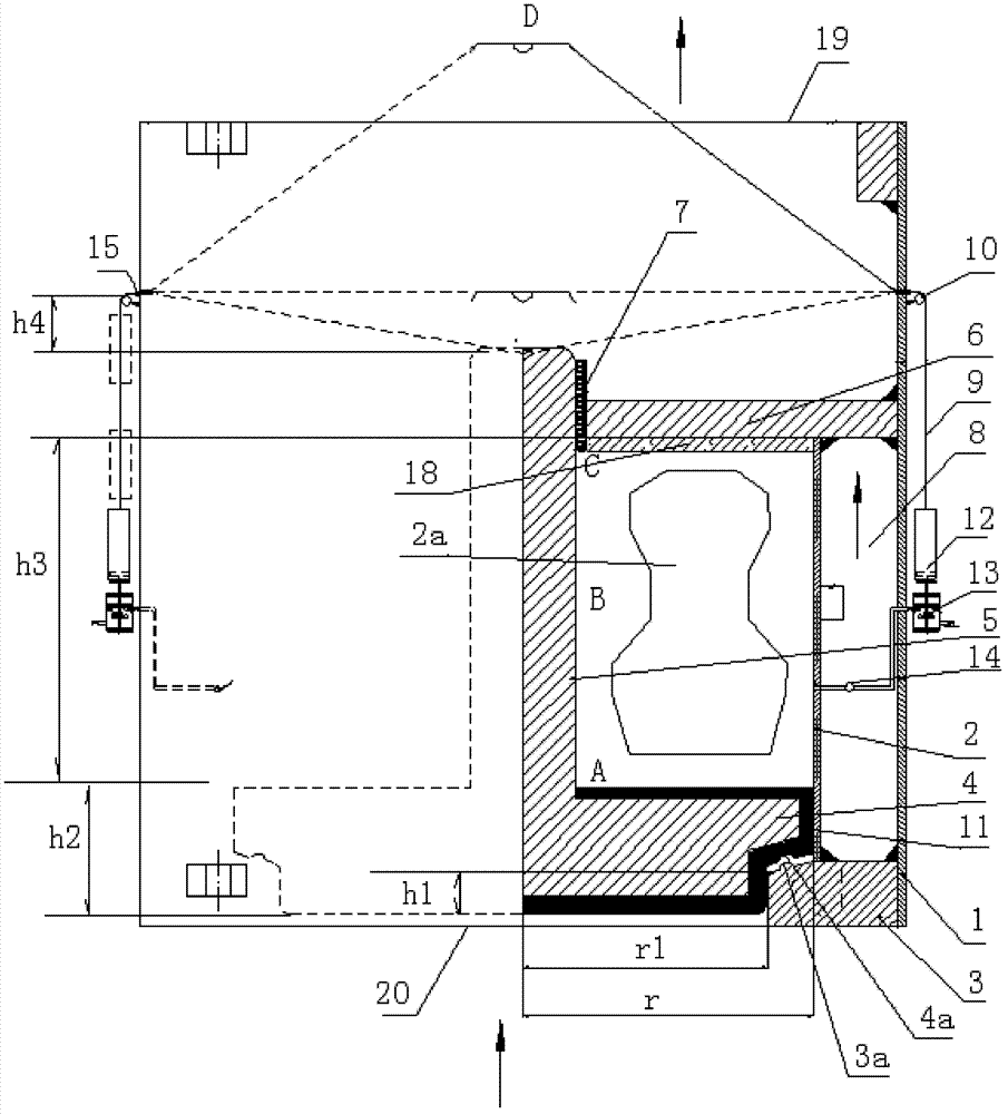
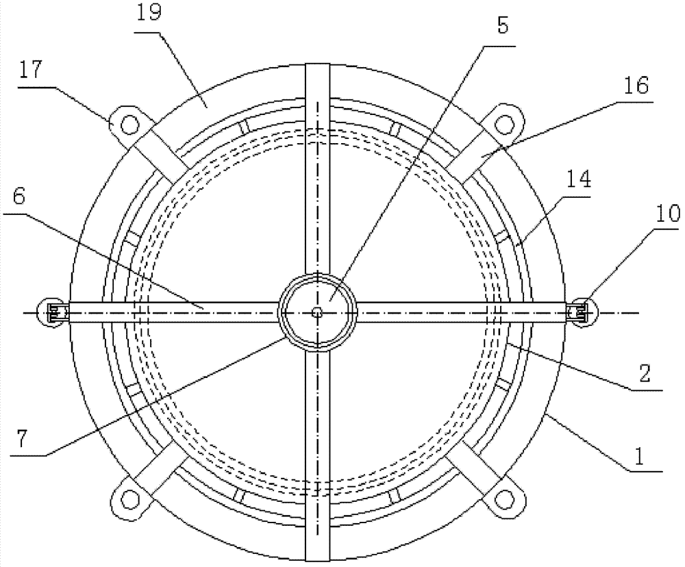
[0029] figure 1 , figure 2 It is a structural representation of the present invention:

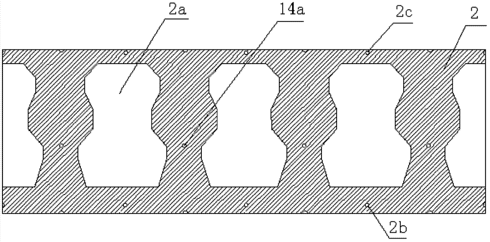
[0030] The ultra-high pressure automatic release device in the gas system pipe network of the present invention includes a cylinder body, a piston in the cylinder body, and a piston rod. The cylinder body includes an outer cylinder 1, and an inner cylinder coaxial with it is arranged in the outer cylinder 1. 2. There is a vent 2a on the inner cylinder 2 to communicate with the inner cylinder 2 and the outer cylinder 1, and the middle annular area 8 of the outer cylinder 1 and the inner cylinder 2 communicates with the upper exhaust port 19 of the outer cylinder 1; the lower port of the outer cylinder 1 is connected to the annular base 3. The upper end face is connected, and the lower port of the inner cylinder 2 is connected with ...


PUM


Abstract

The invention provides an extreme pressure automatic diffusing device in a pipe network of a gas system, which comprises a cylinder, a piston arranged in the cylinder, and a piston rod; an external cylinder is internally provided with an internal cylinder which is coaxial with the external cylinder, the internal cylinder is provided with a diffusing hole with which the internal cylinder and the external cylinder are communicated, and the annular area between the external cylinder and the internal cylinder is communicated with a vent hole on the upper part of the external cylinder; the lower opening of the external cylinder is connected with the upper end face of an annular base, the lower opening of the internal cylinder is connected with the upper end face of the annular base, the inner annular opening of the annular base is an air inlet, the internal cylinder is matched with the diameter of the upper part of the piston, the bottom of the internal cylinder is distributed with a lowervent hole, the piston rod is positioned on the upper part of the piston, the upper part of the piston rod passes through a shaft sleeve, the external side of the shaft sleeve is connected with one end of a fixed cross beam, the other end of the fixed cross beam is connected with the external cylinder, the lower surface of the fixed cross beam is connected with the upper end cover of the internal cylinder, and the edge of the upper end cover of the internal cylinder is connected with the inner side of the internal cylinder; and the top end of the piston rod is connected with one ends of two symmetrical steel wire ropes or four symmetrical steel wire ropes, the steel wire ropes pass through a fixed pulley on the outer side of the external cylinder, the other ends of the steel wire ropes areconnected with a counter weight adjusting block, and the position of the fixed pulley is higher than the top end of the piston rod when the piston is positioned at the bottom.

Description

technical field [0001] The invention relates to an ultra-high pressure automatic release device in a gas system pipe network, which belongs to the technical field of pressure automatic control in the gas pipe network. Background technique [0002] The existing gas automatic release device is composed of valve body, valve cover, connecting rod, counterweight and other components. The principle is that the valve cover and valve body cooperate to seal the gas, and the edge of the valve cover is welded to a connecting rod For connection, the connecting rod forms an angle of 0° to 90° with the horizontal direction. A counterweight is suspended at the end of the far valve cover of the connecting rod. The weight of the counterweight adjusts the release pressure of the gas. When the gas is greater than the release pressure, the bonnet of the release valve is opened at the top to achieve the purpose of automatic release. [0003] This type of valve has the following main problems: ...

Claims


Application Information

Patent Timeline
Patent Type & Authority Patents(China)
IPC IPC(8): F16K17/12F16K17/164F16K47/00F16K51/00B08B3/02
Inventor 付刚朝张静波黄学能高千才
Owner WUHAN IRON & STEEL GRP ECHENG IRON & STEEL CO LTD
Why Eureka
Try Eureka