Rapid testing device for pavement deflection

A road surface deflection and detection device technology, applied in roads, roads, road repairs, etc., can solve the problems of low test speed, slow test speed, waste of road resources, etc., to save time and human resources, improve effective utilization rate, Effect of Personal Safety Guarantee

Inactive Publication Date: 2012-07-04
BEIJING LUXING NEW ROAD TECH
View PDF7 Cites 8 Cited by
  • Summary
  • Abstract
  • Description
  • Claims
  • Application Information

AI Technical Summary

Problems solved by technology

[0007] The existing pavement deflection detection technology has the following disadvantages: 1) The test speed is low. At present, the detection speed of this type of equipment is relatively slow, and the fastest speed will not exceed 7km / h. Compared with other main technical indicators of the road surface For example, there is still a large gap in the detection speed (≥50Km / h) of indicators such as flatness, rutting, and lateral force coefficient; 2) The personal safety of testers cannot be effectively guaranteed
Due to the slow test speed or the need to test under static conditions, rear-end collisions are prone to occur when testing on expressways, causing serious traffic accidents; 3) The deflection values ​​obtained by this type of testing equipment are obtained at slow or It is obtained under static conditions, and there is a certain difference from the effect of vehicles on the road surface during actual road driving; 4) When this type of equipment is tested, it needs to occupy road resources or close traffic, which affects the normal use of the road and causes waste of road resources

Method used


Image

  • Rapid testing device for pavement deflection
  • Rapid testing device for pavement deflection
  • Rapid testing device for pavement deflection

Examples


Embodiment Construction

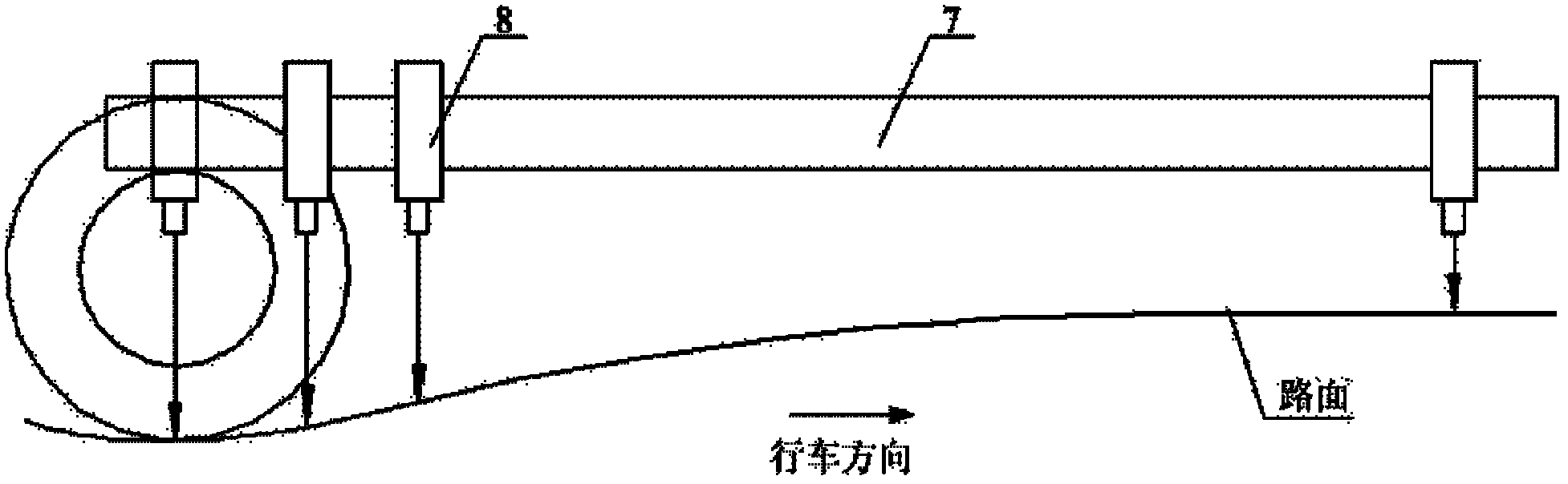
[0025] Such as Figure 1~2 In the shown embodiment, the rapid detection device for road surface deflection according to the present invention includes a rear towed test vehicle 1 and a shock absorption system, and a steel beam support 4 is arranged in the compartment of the test vehicle 1, and the steel beam support 4 is longitudinally arranged The test steel beam 7 is provided with several Doppler laser sensors 8 on the test steel beam 7. The shock absorption system includes a three-stage shock absorption system. The first stage shock absorption system is the test vehicle chassis shock absorption system, and the second stage shock absorption system is Real-time adjustment of the servo control system for testing the posture of the steel beam. The third-level shock absorption system includes a vibration isolation pad 6 arranged between the steel beam support 4 and the bottom of the carriage, and a damping cylinder 11 arranged on the steel beam support 4 to reduce vibration. For...


PUM


Abstract

The invention discloses a rapid testing device for pavement deflection. The rapid testing device comprises a dragging type test vehicle and a shock absorption system; a steel beam bracket is arranged in a compartment of the test vehicle; a testing steel beam is longitudinally arranged on the steel beam bracket; a plurality of Doppler laser sensors are arranged on the testing steel beam; and the shock absorption system comprises three shock absorption systems, wherein a first shock absorption system is a shock absorption system for testing the chassis of the vehicle, a second shock absorption system is a servo control system which is used for adjusting the gesture of the testing steel beam in real time, and a third shock absorption system comprises a shock-isolating cushion arranged between the steel beam bracket and the bottom of the compartment and a damping cylinder arranged on the steel beam bracket. With the adoption of the rapid testing device, the testing efficiency is increased, the time and the human resources of road testing departments are saved, and the testing is carried out on an express way at a normal running speed, so that the personnel safety of workers is effectively ensured; meanwhile, no lanes are occupied or the traffic is not closed, so that the road resources are saved, and the effective utilization ratio of a road when the deflection testing is carried out is improved.

Description

technical field [0001] The invention relates to the field of road surface deflection detection, in particular to a rapid detection device for road surface deflection. Background technique [0002] Deflection is a parameter that characterizes the overall strength of the roadbed and pavement. It generally refers to the total vertical deformation (total deflection) or the vertical rebound deformation value (rebound deflection) of the wheel gap position on the surface of the roadbed or pavement under the specified standard load. Taking 0.01mm as the unit, pavement deflection is an important technical index to characterize the structural strength of pavement, and it is an important item that must be tested in construction acceptance, pavement evaluation and maintenance management. [0003] Since 1951, Beckman has designed a beam arm instrument Beckman Beam (BenkeLman Beam) combined with a dial gauge for the Western Association of Highway Workers (WASHO) in Idaho to test the road ...

Claims


Application Information

Patent Timeline
Patent Type & Authority Applications(China)
IPC IPC(8): E01C23/01
Inventor 呼六福候君辉吴智山李孝兵
Owner BEIJING LUXING NEW ROAD TECH
Why Eureka
Try Eureka