Diamond cutter slow-feeding and fast-retracting device based on air static pressure guide rail component

A technology of diamond tools and aerostatic pressure, which is used in grinding drive devices, parts of grinding machine tools, manufacturing tools, etc. problem, to achieve the effect of simple and accurate slow forward and fast backward operation, self-locking, high-precision repeated positioning

Active Publication Date: 2013-08-07
HARBIN INST OF TECH
View PDF7 Cites 0 Cited by
  • Summary
  • Abstract
  • Description
  • Claims
  • Application Information

AI Technical Summary

Problems solved by technology

[0005] The purpose of the present invention is to solve the problem that there is no device capable of realizing the high-precision grinding of diamond tools and the slow-forward and fast-reverse functions in fast on-site measurement so far, and to provide a high-precision and easy-to-operate device based on air static pressure Diamond tool slow forward and fast reverse device for guide rail components

Method used


Image

  • Diamond cutter slow-feeding and fast-retracting device based on air static pressure guide rail component
  • Diamond cutter slow-feeding and fast-retracting device based on air static pressure guide rail component
  • Diamond cutter slow-feeding and fast-retracting device based on air static pressure guide rail component

Examples


specific Embodiment approach 1

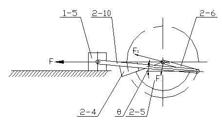
[0022] Specific implementation mode one: as Figure 1-Figure 9 , a diamond tool slow-forward and fast-reverse device based on an aerostatic guideway component, the device includes an aerostatic guideway component 1, a slow-forward and fast-reverse component 2, and a machine tool base 3,

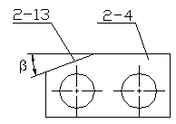
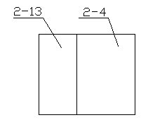
[0023]The slow-forward and fast-rewind part 2 includes an operating hand wheel 2-1, an extension rod 2-2, a bearing support seat 2-3 with a built-in diagonal contact bearing, a limit block 2-4, a sector block 2-5, a short Connecting rod 2-6, guide rail connector 2-7, first bearing 2-9, long connecting rod 2-10, second bearing 2-11; aerostatic guide rail part 1 and slow forward and fast rewind part 2 all set On the upper surface of the machine tool base 3, the middle part of the upper surface of the machine tool base 3 is provided with a through long groove 3-1 along its width direction, and the left side of the machine tool base 3 near the front end of the left side is along the The length d...

specific Embodiment approach 2

[0026] Specific implementation mode two: as figure 1 , image 3 and Figure 6a-Figure 6c , Specific Embodiment 1 A diamond cutter slow-forward and fast-reverse device based on aerostatic guideway components, the aerostatic guideway component 1 includes slide plates 1-5, four thrust plates and a plurality of small Orifice restrictor 1-4, four thrust plates are left side thrust plate 1-1, right side thrust plate 1-7, left upper thrust plate 1-3 and right upper thrust plate 1-6, slide The plate 1-5 is located in the middle of the upper surface of the machine base 3, the left side of the slide plate 1-5 is integrally formed with a left boss 1-9, and the right side of the slide plate 1-5 is integrally formed with a right boss 1 -10, the left thrust plate 1-1 is located on the left side of the left boss 1-9, the right thrust plate 1-7 is located on the right side of the right boss 1-10, and the left upper thrust plate 1-3 is placed on On the left side thrust plate 1-1 and the lef...


PUM

PropertyMeasurementUnit
friction coefficientaaaaaaaaaa

Abstract

The invention relates to a diamond cutter slow-feeding and fast-retracting device based on an air static pressure guide rail component and belongs to the technical field of ultra-precision processing. Up to now, no slow-feeding and fast-retracting device capable of realizing the high-precision grinding and the fast in-suit measurement of a diamond cutter exists. The air static pressure guide railcomponent and the slow-feeding and fast-retracting device are arranged on a machine tool base, a long hole of the machine tool base is communicated with a long groove, an extending rod penetrates into the long hole and is supported through a bearing support seat, the bearing support seat is fixedly connected with the long groove, one ends of a fan-shaped baffle block and a short connecting rod are respectively nested on the extending rod, a position limiting block is fixedly arranged on a bearing support seat and is provided with an inclined surface, the fan-shaped baffle block and the position limiting block are in relative arrangement in the radial direction of the extending rod, a long connecting rod is arranged in the long groove, rotating pairs are formed between a short connecting rod and the long connecting rod as well as between the long connecting rod and a guide rail connecting element, the guide rail connecting element is fixedly connected with a slide carriage of the air static pressure guide rail component, and the extending rod is fixedly connected with an operation hand wheel. The diamond cutter slow-feeding and fast-retracting device is used for the high-precision grinding and the slow-feeding and fast-retracting operation of the diamond cutter.

Description

technical field [0001] The invention belongs to the technical field of ultra-precision machining, and relates to a slow-forward and fast-backward device for a diamond tool. Background technique [0002] Ultra-precision machining technology is an advanced manufacturing technology developed in the 1960s specifically to meet the needs of modern high-tech. It is a new mechanical processing technology that challenges the high-precision limit that traditional processing methods are not easy to break through. Ultra-precision machining technology integrates cutting-edge technologies in the fields of electronics, sensing, optics, control and measurement, and is the basic technology in the high-tech field. With the application and promotion of ultra-precision machining technology, the precision of machining has been improved by 1 to 3 orders of magnitude in a few decades, and it is developing towards higher precision nanometer precision. Industrially developed countries such as Japan...

Claims


Application Information

Patent Timeline
Patent Type & Authority Patents(China)
IPC IPC(8): B24B47/20B24B3/00
Inventor 李增强宗文俊孙涛赵学森
Owner HARBIN INST OF TECH
Why Eureka
Try Eureka