Two-fluid jet system

An injection system and two-fluid technology, applied in liquid injection devices, injection devices, etc., can solve the problems of increasing the wear of the injection needle and valve body, reducing the dispensing accuracy and service life of the equipment, and difficult maintenance.

Inactive Publication Date: 2012-07-04
SHANGHAI UNIV
View PDF5 Cites 20 Cited by
  • Summary
  • Abstract
  • Description
  • Claims
  • Application Information

AI Technical Summary

Problems solved by technology

[0004] At present, whether the jet dispensing equipment uses high-pressure gas to drive the mechanical needle, or the electromagnet, piezoelectric ceramics, or diaphragm pump to drive the needle, there are several main problems: 1. There are moving parts in the dispensing head (such as: Needle) exists, relying on the collision between the moving parts and the dispensing head cavity to realize the process of spraying glue from the dispensing head to the substrate, due to the existence of mechanical collision, the wear of the needle and valve body is increased, and the point of the equipment is reduced Glue accuracy and service life; 2. The reciprocating motion of the spray needle will cause the viscous fluid material to rub against it and cause wear, which will reduce the movement accuracy, sealing and size consistency of the spray glue point of the spray needle; 3. The mechanical structure of the spray dispensing equipment More complex and more difficult to maintain

Method used


Image

  • Two-fluid jet system
  • Two-fluid jet system
  • Two-fluid jet system

Examples


Embodiment 1

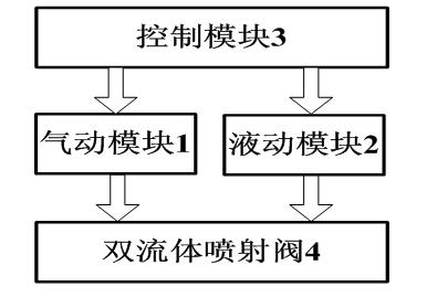
[0060] Embodiment one: refer to figure 1 , the dual-fluid injection system includes a pneumatic module (1), a hydraulic module (2), a control module (3), and a dual-fluid injection valve (4). The control signal input / output ports of the pneumatic module (1) and the hydraulic module (2) are respectively connected to the control module (3), and the flow and pressure of the output gas and liquid are controlled by the control module (3), and the pneumatic module (1) and the working medium output ports of the hydraulic module (2) are respectively connected to the gas and liquid inlets of the dual-fluid injection valve (4), and this system realizes the injection of liquid materials.

Embodiment 2

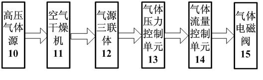
[0061] Embodiment two: refer to figure 1 and figure 2 , this embodiment is basically the same as Embodiment 1, and the special feature is that the pneumatic module (1) is a subsystem of the dual-fluid injection system, which is provided with a high-pressure gas source (10), an air dryer (11), and a gas source in sequence. Triple body (12), gas pressure control unit (13), gas flow control unit (14), gas solenoid valve (15), there are φ6-M5 push-in connectors and φ6 hose connections between each component, This subsystem realizes the supply of working medium—gas.

Embodiment 3

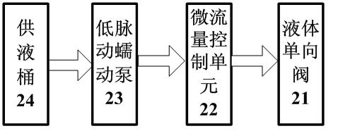
[0062] Embodiment three: refer to figure 1 and image 3 , this embodiment is basically the same as Embodiment 1, and the special feature is that the hydraulic module (2) is a subsystem of a dual-fluid injection system, which is sequentially provided with a liquid supply barrel (24), a low-pulsation peristaltic pump (23), The micro-flow control unit (22), the liquid solenoid valve (21), and the components are connected with φ6-M5 quick-plug connectors and φ6 hoses, and this subsystem realizes the supply of the working medium—liquid.


PUM


Abstract

The invention relates to a two-fluid jet system, which comprises a pneumatic module, a hydraulic module, a control module and a two-fluid jet valve, wherein the control module is respectively connected with a gas pipe and a liquid pipe of the two-fluid jet valve through the pneumatic module and the hydraulic module. The two-fluid jet system is based on the microchannel gas-liquid flow movement principle, namely the control module is used for controlling gas-liquid flow velocity ratio or flow ratio of the pneumatic module and the hydraulic module, so that liquid jet of slug flow is realized in a microchannel. The two-fluid jet system is applicable to fluid jet in the fields of semiconductor film preparation, composite preparation, electronic package, MEMS (micro-electromechanical systems), spraying, ink jet, powder metallurgy, biomedicine, food processing, welding, combustion, chemical engineering and the like.

Description

technical field [0001] The invention relates to a dual-fluid injection system, in particular to a non-contact injection system with high precision, high consistency, micro volume (nanoliter), fast response, good controllability, and good applicability (low viscosity, high viscosity liquid). dual-fluid injection system. It can be widely used in the injection of multi-fluid in the fields of semiconductor thin film preparation, composite material preparation, electronic packaging, MEMS system, inkjet, spray coating, powder metallurgy, biomedicine, food processing, welding, rapid prototyping, combustion, chemical industry, engine, etc. craft. Background technique [0002] The invention originates from the research on the glue injection technology in the field of electronic packaging. [0003] Electronic packaging technology is an important part of today's semiconductor manufacturing industry. It continues to develop with the miniaturization and integration of semiconductor th...

Claims


Application Information

Patent Timeline
IPC IPC(8): B05B7/04B05B12/00
Inventor 张金松王志亮彭鹏张建华
Owner SHANGHAI UNIV
Why Eureka
Try Eureka