
Plasma ejection device for igniting long air spark gap and circuit thereof

A technology of plasma and spray device, applied in the field of plasma spray device, can solve the problem of non-reusable, etc., and achieve the effects of easy ignition, high working reliability, and improved dispersibility

Active Publication Date: 2014-08-06
西安西交瑞力电气研究院有限公司
View PDF5 Cites 0 Cited by
  • Summary
  • Abstract
  • Description
  • Claims
  • Application Information

AI Technical Summary

Problems solved by technology

[0006] Aiming at the deficiency of above-mentioned traditional ignition method, the purpose of the present invention is to propose a kind of plasma injection device that is used for reliably igniting long air spark gap, plasma injection device is based on traditional capillary discharge, carries out on structure and circuit The improved design overcomes the defect that the traditional capillary discharge plasma injection device cannot be reused

Method used


Image

  • Plasma ejection device for igniting long air spark gap and circuit thereof
  • Plasma ejection device for igniting long air spark gap and circuit thereof
  • Plasma ejection device for igniting long air spark gap and circuit thereof

Examples


Embodiment 1

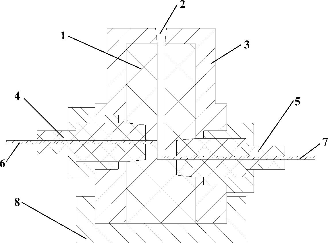
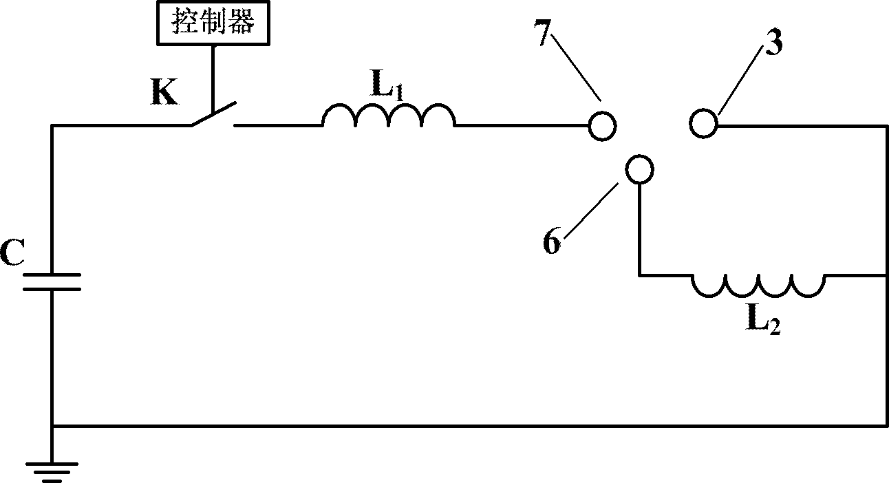
[0034] This embodiment is a plasma injection device for igniting a long air spark gap, and its structural schematic diagram and discharge circuit schematic diagram are as follows figure 2 and image 3 shown. 3 and 8 are metal shells, the gas-generating material 1 is high-density polyethylene, the high-voltage electrode 7 and low-voltage electrode 6 are 1 mm ablation-resistant metal rods, and the insulating sleeves 4 and 5 are made of high-density polyethylene. When using interference fit, each component can achieve a tight fit. The length of the short gap channel is 1mm; the length of the gap channel is 5mm, and the channel diameter is 1mm; the full angle of the nozzle cone angle of the injection device is 8°; the capacity of the discharge capacitor C is 5μF, and the charging voltage is 3kV; the discharge inductance L 2 is 10μH.

Embodiment 2

[0036] This embodiment is a plasma injection device for igniting a long air spark gap, and its structural schematic diagram and discharge circuit schematic diagram are as follows figure 2 and image 3 shown. 3 and 8 are metal shells, the gas-generating material 1 is polycarbonate, the high-voltage electrode 7 and the low-voltage electrode 6 are ablation-resistant metal rods of 2mm, and the insulating sleeves 4 and 5 are made of nylon material, and the over-molding is used during assembly. Surplus assembly, so that each component achieves a tight fit. The length of the short gap channel is 4mm; the length of the gap channel is 30mm, and the channel diameter is 3mm; 2 is 40μH.

Embodiment 3

[0038] This embodiment is a plasma injection device for igniting a long air spark gap, and its structural schematic diagram and discharge circuit schematic diagram are as follows figure 2 and image 3 shown. 3 and 8 are metal shells, the gas-generating material 1 is PMMA, the high-voltage electrode 7 and the low-voltage electrode 6 are 2mm ablation-resistant metal rods, and the insulating sleeves 4 and 5 are made of nylon material, and the interference is used when assembling Assemble so that the various components achieve a tight fit. The length of the short gap channel is 5mm; the length of the gap channel is 50mm, and the channel diameter is 5mm; 2 is 80μH.


PUM


Abstract

The invention discloses a long air spark gap ignition mechanism. The long air spark gap ignition mechanism is characterized in that a high-energy plasma ejection device is mounted on one electrode column of the spark gap. The plasma ejection device comprises a high-voltage electrode, an intermediate-voltage electrode and a low-voltage electrode, wherein the intermediate-voltage electrode divides a flashover gap channel into a short gap channel and a long gap channel; and the intermediate-voltage electrode and the low-voltage electrode are connected an inductor therebetween to serve as a voltage division unit and an energy storage unit of a discharge circuit. The inductor is used as the voltage division unit at the initial discharge period, and then is used as the energy storage unit to achieve follow current of long gap channel arc after the energy of a discharge capacitor is released completely. The plasma ejection device can stably eject a large amount of plasma under lower discharge voltage multiple times, and the plasma ejection speed exceeds sound velocity by multiple times. The plasma ejection device can be used repeatedly with substantially no performance change after repeated ejection, and can reliably ignite and breakdown the long air spark gap.

Description

Technical field: [0001] The patent of the invention belongs to the technical field of pulse power, and specifically relates to a plasma injection device for igniting a long air spark gap. Background technique: [0002] The long air spark gap is used as the switching element of the high-voltage pulse forming network, the steepening switch of the high-voltage pulse or the overvoltage protection gap of the power equipment, and the forced trigger method is often used to make it break down reliably. The forced trigger method is adopted, on the one hand, because under atmospheric conditions, the self-breakdown voltage is greatly affected by air humidity, temperature and pressure, that is, the self-breakdown performance is unstable; The spark gap can be reliably broken down under certain conditions. [0003] For the research on forced trigger breakdown of long air spark gap under DC high voltage or pulse high voltage, a lot of experiments have been done at home and abroad, and suf...

Claims


Application Information

Patent Timeline
Patent Type & Authority Patents(China)
IPC IPC(8): H05H1/32
Inventor 杨兰均黄东吴伟张皓维徐然张玲玲
Owner 西安西交瑞力电气研究院有限公司
Learn More