
Method for detecting surface figures of large-aperture off-axis convex aspheric mirror

A detection method and reflective mirror technology, applied in measuring devices, instruments, optical devices, etc., can solve problems such as complex structure, large compensator aperture, and large number of sub-apertures

Active Publication Date: 2013-11-27
CHANGCHUN INST OF OPTICS FINE MECHANICS & PHYSICS CHINESE ACAD OF SCI
View PDF3 Cites 0 Cited by
  • Summary
  • Abstract
  • Description
  • Claims
  • Application Information

AI Technical Summary

Problems solved by technology

However, the design of a convex aspheric compensator is much more complicated than that of a concave aspheric compensator. A convex aspheric compensator must be composed of at least two lenses. Sometimes the compensator itself may contain aspheric elements. To achieve The high-precision detection of the aspheric surface needs to design a set of compensators for it, which brings a lot of difficulties to the processing and assembly.
In addition, zero compensation by computational holography (CGH) can better realize the detection of aspheric surfaces, but for aspheric surfaces with high steepness and large deviation, the linear frequency density of computational holography is very high, so that it can describe making impossible
In addition, since the detection of a convex aspheric surface needs to converge the wavefront as a reference wavefront, this requires that the aperture of the interferometer used and the aperture of the compensation lens or CGH be larger than the aperture of the convex aspheric surface to be tested, and the production of large-diameter compensation lenses and CGH There are still many difficulties in adjusting and adjusting
[0005] It can be concluded that, in order to complete the detection of large-diameter off-axis convex aspheric surfaces, one of the most conventional methods is to make a zero-position compensation lens, but the compensator will consist of several lenses, the structure is complex, and the compensation lens itself may still be large. In addition, the aperture of the compensator will be very large, so there are many bottlenecks in this method; another conventional method is to make a diffraction element and calculate holography to complete its measurement, but for a convex aspheric surface with a large deviation and a large aperture, it needs Fabrication of computational holographic elements with large aperture and high line frequency density. At present, computational holographic production is limited by aperture and frequency density of scribed lines, which makes this method difficult to realize.
In addition, the sub-aperture stitching method is used to measure the phase distribution of multiple sub-apertures. The stitching measurement of shallow convex aspheric surfaces can be completed through the sub-aperture stitching algorithm. There are many numbers, the operation is very complicated, and it will inevitably lead to the transfer and accumulation of splicing errors

Method used


Image

  • Method for detecting surface figures of large-aperture off-axis convex aspheric mirror
  • Method for detecting surface figures of large-aperture off-axis convex aspheric mirror
  • Method for detecting surface figures of large-aperture off-axis convex aspheric mirror

Examples


Embodiment Construction

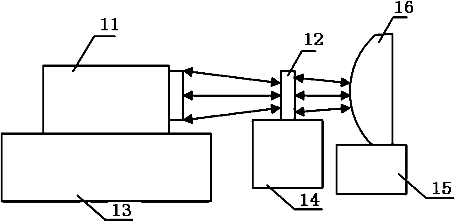
[0042] like figure 1 As shown, the device for realizing the large-diameter off-axis convex aspheric mirror surface shape detection method of the present invention includes a laser interferometer 11, a calculation holographic element 12, a first adjustment mechanism 13, a second adjustment mechanism 14, a third adjustment mechanism 15 and The large-diameter off-axis convex aspheric surface 16 to be tested.

[0043] The first adjustment mechanism 13 adopts a currently known three-dimensional precision adjustment frame, which can accurately control the translation of the interferometer 11 along the X direction, the Y direction and the Z direction (optical axis direction). The second adjustment mechanism 14 adopts a currently known six-dimensional precision adjustment frame, which can accurately adjust the pitch, yaw, and rotation of the computational holographic element 12, as well as the translation along the X direction, Y direction, and Z direction (optical axis direction). T...


PUM


Abstract

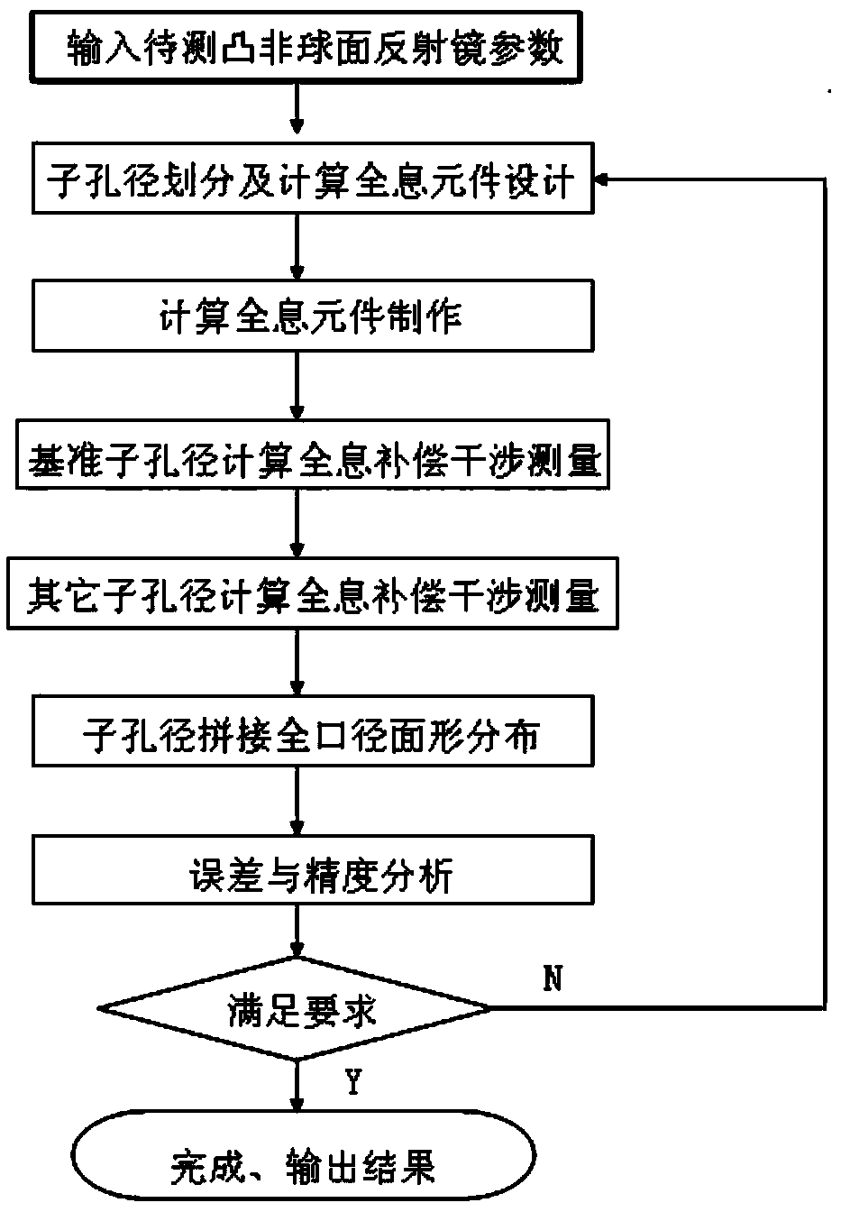
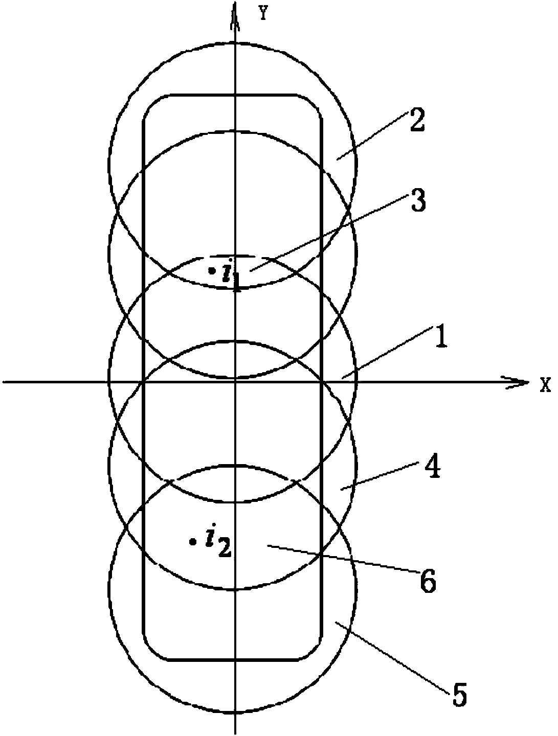
The invention relates to a method for detecting surface figures of a large-aperture off-axis convex aspheric mirror. The method comprises the following steps of: performing null interferometry on reference sub-aperture regions by using computer-generated holographic elements which correspond to surface figures of the reference sub-aperture regions of an aspheric mirror to be detected; performing null interferometry on off-axis sub-aperture regions by using computer-generated holographic elements which correspond to surface figures of the off-axis sub-aperture regions of the aspheric mirror to be detected: solving the distribution of full-aperture surface figures of the convex aspheric mirror to be detected; converting coordinates of all off-axis sub-apertures in an x-y-z coordinate system into coordinates below an X-Y-Z coordinate system and obtaining the distribution of full-aperture phases of the convex aspheric mirror to be detected by calculation; and removing system adjustment errors from the distribution of the full-aperture phases to obtain the error distribution of the full-aperture surface figures of the convex aspheric mirror to be detected. The invention has the advantages of simple data processing and mathematical operation, easy experiment operation, low detection cost and short testing time.

Description

technical field [0001] The invention relates to a method for detecting the surface shape of an optical aspheric surface, in particular to a method for detecting the surface shape of a large-diameter off-axis convex aspheric mirror. Background technique [0002] The use of aspherical elements in optical systems can correct aberrations, improve image quality, and reduce the size and weight of optical systems. Therefore, aspheric optical elements are being used more and more in various fields. In many application fields, convex aspheric elements are more commonly used core components. [0003] However, the measurement of convex aspheric surface shape has always been a difficult point in optical inspection. In the past, we generally used the aberration-free point method to measure it. The essence is: if the surface to be tested is ideal, and the point light source is accurately placed on one of them At the geometric focus, the light reflected by the surface forms a spherical wa...

Claims


Application Information

Patent Timeline
Patent Type & Authority Patents(China)
IPC IPC(8): G01B11/24
Inventor 王孝坤黎发志郑立功张学军
Owner CHANGCHUN INST OF OPTICS FINE MECHANICS & PHYSICS CHINESE ACAD OF SCI
Learn More