
Optically annular lighting device

A ring lighting and optical technology, applied in lighting devices, lighting device parts, optics, etc., can solve the problem of inability to provide high-power optical ring beams, and achieve a wide range of working wavelengths, rational use of energy, and easy installation and debugging. Effect

Inactive Publication Date: 2012-06-27
XIAMEN UNIV
View PDF5 Cites 11 Cited by
  • Summary
  • Abstract
  • Description
  • Claims
  • Application Information

AI Technical Summary

Problems solved by technology

[0006] The purpose of the present invention is to provide an optical ring lighting device to address the shortcomings of the prior art that cannot provide high-power optical ring beams.

Method used


Image

  • Optically annular lighting device
  • Optically annular lighting device
  • Optically annular lighting device

Examples


Embodiment Construction

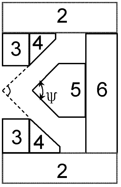
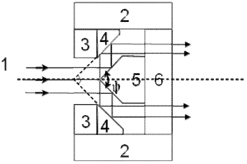
[0022] The following combination Figure 1~3 The optical ring lighting device of the present invention will be further described in detail. It should be understood that the specific embodiments described here are only used to explain the present invention, not to limit the present invention.

[0023] Embodiments of the present invention are provided with a mechanical adjustment frame 2, a first fixed frame 3, an inner conical reflector 4, a conical reflector 5 and a second fixed frame 6; the mechanical adjustment frame 2 is provided with threads, and the first 1 The fixing frame 3 and the second fixing frame 6 are embedded in the mechanical adjustment frame 2, the inner conical reflector 4 is fixed on the first fixing frame 3, and the conical reflecting mirror 5 is fixed on the second fixing frame 6.

[0024] The conical reflector 5 is a conical reflector with a cone angle ψ=90°.

[0025] The mechanical adjustment frame 2 is used for fixing and moving the fixed frame of the ...


PUM


Abstract

The invention discloses an optically annular lighting device, and relates to a lighting device. The optically annular lighting device is provided with a mechanical adjusting frame, a first fixing frame, an inner conical surface reflecting mirror, a conical surface reflecting mirror and a second fixing frame, wherein the mechanical adjusting frame is internally provided with a screw thread, the first fixing frame and the second fixing frame are embedded into the mechanical adjusting frame, the inner conical surface reflecting mirror is fixed on the first fixing frame, and the conical surface reflecting mirror is fixed on the second fixing frame. According to the invention, the energy of an emergent annular light beam basically has no loss compared with that of an incident light ray; the optically annular lighting device basically has no phenomena such as chromatic dispersion, spherical aberration and has a wide range of working wavelengths; the structure of the conical surface reflecting mirror is simple and is easy to process; and the optically annular lighting device can be matched with any objective lens with different backlight aperture sizes, can continuously adjust the angle of an incident excited light and the line diameter size of the emergent annular light beam, and is suitable for the fields of fluorescent light and Raman experiment researches such as high angle SPR (surface Plasmon resonance) excitation, ATR (attenuated total reflectance), super-resolution optical microscopes and the occasions such as advertisement demonstration, stage demonstration.

Description

technical field [0001] The invention relates to an illuminating device, in particular to an optical ring illuminating device. Background technique [0002] Dark field microscopy has been widely used. Its characteristics are different from bright field illumination. It does not directly observe the light of illumination, but observes the light scattered by the object under inspection. Therefore, the field of view becomes a dark background, while the object under inspection presents a bright image. Since the scattered signal is much weaker than the excitation light, in order to ensure a dark field background, a high-angle incident ring beam is required to ensure that the reflected excitation light will not enter the collection lens. [0003] Since most of the central light is blocked, in order to ensure sufficient brightness of the field of view, the instrument manufacturer designed and increased the power of the lighting source, but this method did not make reasonable use of...

Claims


Application Information

Patent Timeline
Patent Type & Authority Applications(China)
IPC IPC(8): F21S2/00F21V14/04G02B21/10G02B5/10G02B27/09
Inventor 任斌沈炜曾智聪王翔
Owner XIAMEN UNIV
Learn More