A method of absorbing material energy and its application

A material energy and energy technology, applied in the fields of refrigeration technology, thermal energy utilization technology and power generation technology, can solve the problem of consuming large energy (electricity, impossible to generate electricity, etc.

Active Publication Date: 2016-12-14
漳州市阿思星谷电子科技有限公司
View PDF5 Cites 0 Cited by
  • Summary
  • Abstract
  • Description
  • Claims
  • Application Information

AI Technical Summary

Problems solved by technology

Taking the traditional refrigeration technology as an example, although it can absorb the energy of air at normal temperature, even in an environment far below normal temperature (such as: freezer), it needs to consume a lot of energy (electric energy), let alone generate electricity from it

Method used


Image

  • A method of absorbing material energy and its application
  • A method of absorbing material energy and its application
  • A method of absorbing material energy and its application

Examples


Embodiment 1

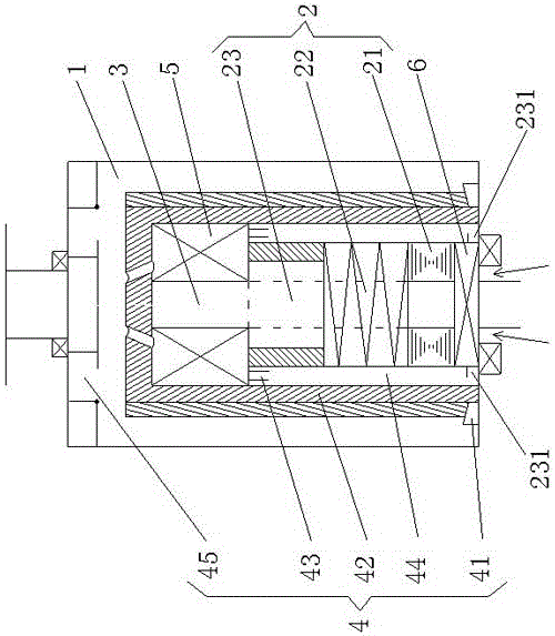
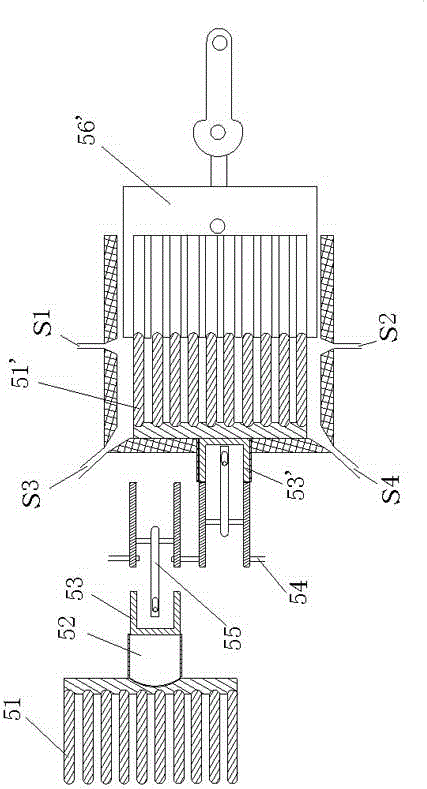
[0054] Such as figure 1 , figure 2 , image 3 The shown self-cooling equipment includes an evaporation chamber 1, a compression system 2, a condensation chamber 3, a refrigerant circulation system 4, a thermodynamic system, and a storage battery 6; the thermodynamic system includes a set of thermodynamic mechanisms 5, Thermodynamic device of thermodynamic mechanism 5'.

[0055] Described thermodynamic mechanism 5 comprises: 100 copper condensing pipes 51, cylinder 52, piston 53, crank 54, connecting rod 55; 52 and piston 53 form a fully enclosed space; 100 condensation pipes 51 are all completely installed in the condensation chamber 3, and are not communicated with the condensation chamber, so that the reaction medium in the condensation pipe 51 will not flow into the condensation chamber 3 except the condensation pipe 51 space, the reaction medium in the same condensation chamber 3 will not flow into the condensation pipe 51, and at the same time, it can ensure sufficien...

Embodiment 2

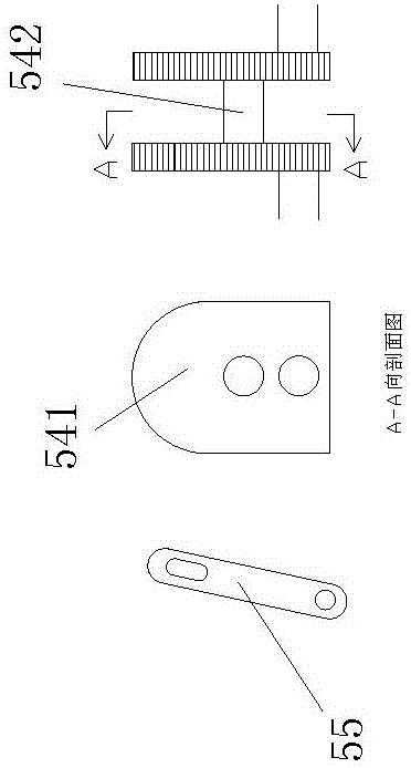
[0099] Such as figure 1 , image 3 , Figure 4 As shown, the thermal power mechanism of Embodiment 1 can also be directly connected to the cylinder 57 by the heat collection chamber 23. When the piston 53 reaches the closest point, K1 is opened, and when the arc section of the cam 541 is turned out of the piston 53, K1 is closed, and the high temperature The high-pressure liquid ammonia vaporizes quickly, and turns into high-pressure gaseous ammonia, which quickly acts on the piston to move to the farthest point; when the piston 53 reaches the farthest point, K2 opens, and the piston 53 discharges the gaseous ammonia out of the cylinder 57, and returns to the compression mechanism through the return pipe 46 . On the other hand, the heat collecting chamber 23 communicates with the preparation chamber 45 through 100 condensation pipes 58 placed in the cooling chamber 44 .

[0100] Such as Figure 5 As shown, with regard to the above-mentioned embodiment, the present inventio...


PUM


Abstract

The present invention provides a method for extracting material energy and its application, wherein: the method for extracting material energy includes the following steps: Step 1 uses the system to do work on one or more media to make it have a certain potential energy; Step 2 makes the above 1 or more mediums undergo physical or chemical changes, and satisfy the following requirements: heat must be absorbed during the change process; and the change only absorbs the heat of the substance; step 3 recovers the reacted medium or recovers the reacted medium in stages, And before the total energy loss of the system is less than the energy obtained in step 2, use the total energy in the system to restore the reaction medium to the state of step 1; and store the energy increased in this step relative to step 1 in a certain form. The present invention utilizes a reaction medium with a certain potential energy to undergo a reversible physical or chemical reaction to absorb the heat of the contacted substance; through the cooling medium, the cooling medium fully contacts each working component, and compresses the cooling medium that carries the heat of each heating component of the present invention, so that its temperature After the increase, it is converted into the power source of each working part of the present invention, and will be converted into storable energy.

Description

technical field [0001] The invention mainly relates to a method for extracting material energy, and in particular to refrigeration technology, heat energy utilization technology and power generation technology using the method. Background technique [0002] At present, there is no technology to generate electricity without absorbing the heat energy of matter at room temperature. Taking traditional refrigeration technology as an example, although it can absorb the energy of air at normal temperature, even in an environment far below normal temperature (such as: freezer), it needs to consume a lot of energy (electrical energy), let alone generate electricity. Contents of the invention [0003] The purpose of the present invention is to solve the above problems, and provide a method for extracting material energy, and low energy consumption refrigeration equipment and thermal power generation equipment using the method. [0004] Glossary: [0005] Reaction medium: A medium ...

Claims


Application Information

Patent Timeline
Patent Type & Authority Patents(China)
IPC IPC(8): F01K25/10F25B1/00
Inventor 黄得锋
Owner 漳州市阿思星谷电子科技有限公司
Why Eureka
Try Eureka