Integrated exhaust gas recovery device

A waste gas recovery and integrated technology, applied in the direction of vapor condensation, dispersed particle separation, chemical instruments and methods, etc., can solve problems such as difficult work, save on-site design and on-site construction, shorten project construction period, and improve reliability. Effect

Active Publication Date: 2013-08-28
连云港远洋流体装卸设备有限公司
View PDF4 Cites 2 Cited by
  • Summary
  • Abstract
  • Description
  • Claims
  • Application Information

AI Technical Summary

Problems solved by technology

In the past, many welding and other workloads of equipment were completed at the customer's site, and chemical companies all required explosion-proof requirements, so the work was difficult, and safety measures in the workplace must be complete

Method used


Image

  • Integrated exhaust gas recovery device
  • Integrated exhaust gas recovery device
  • Integrated exhaust gas recovery device

Examples


Embodiment Construction

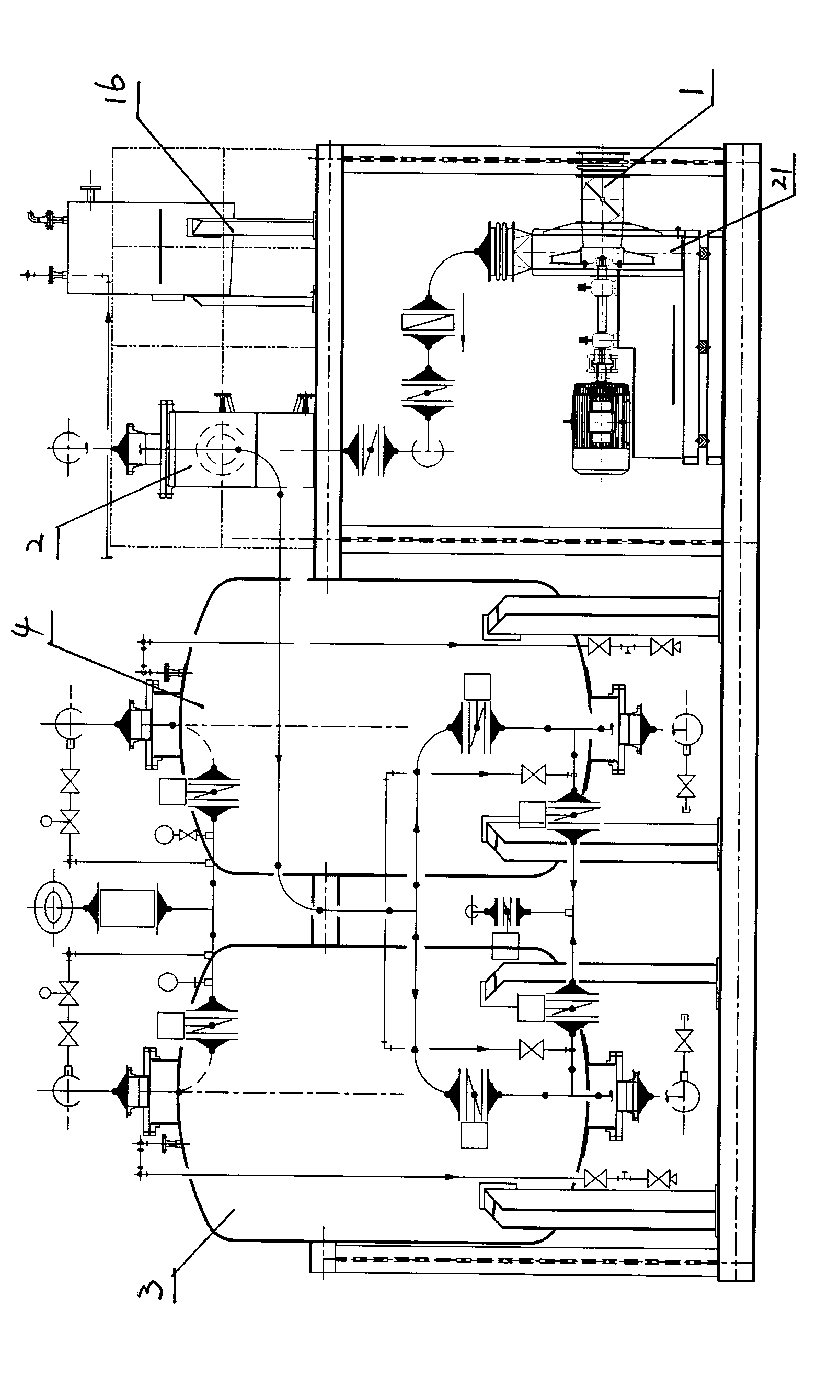
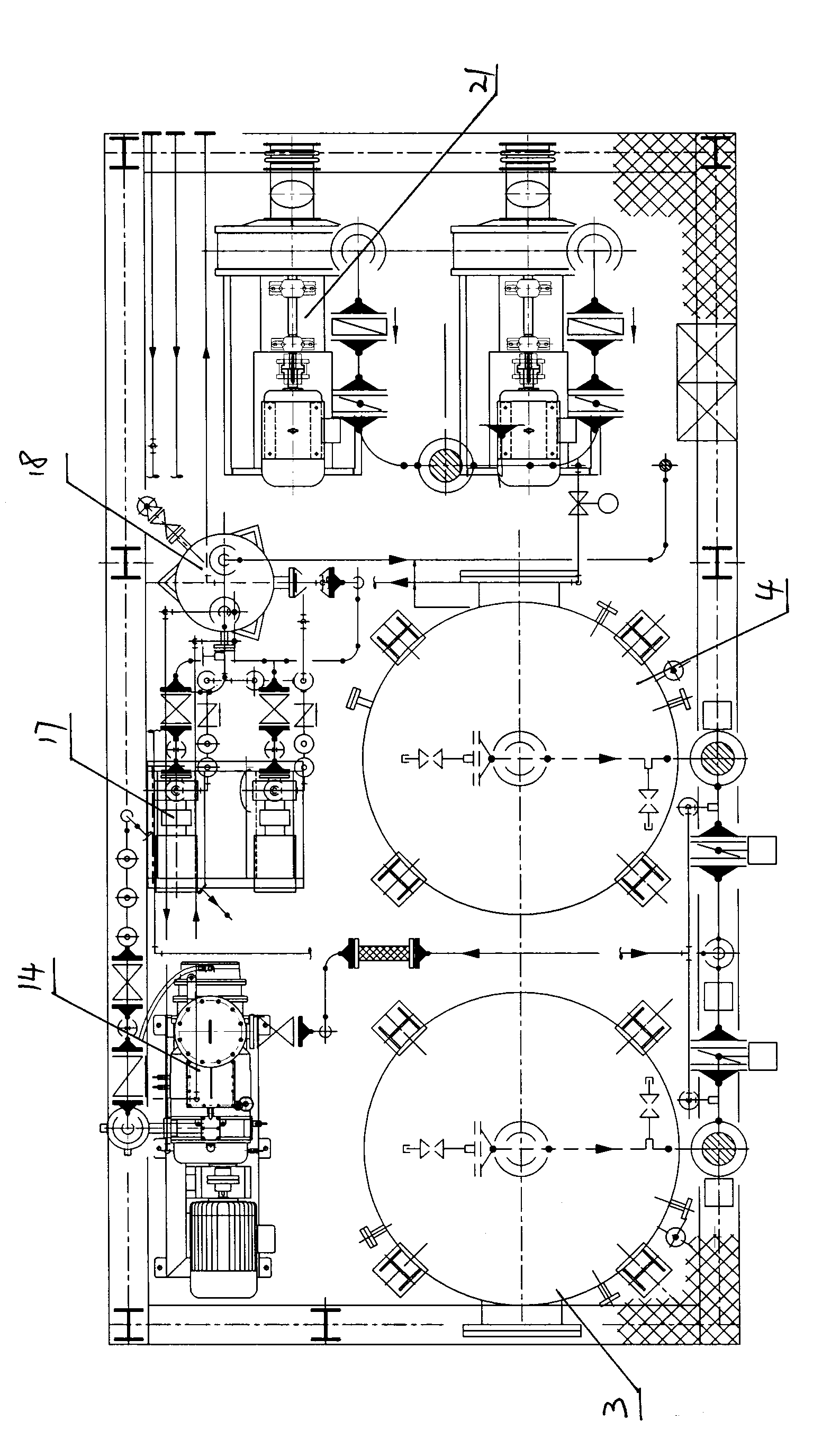
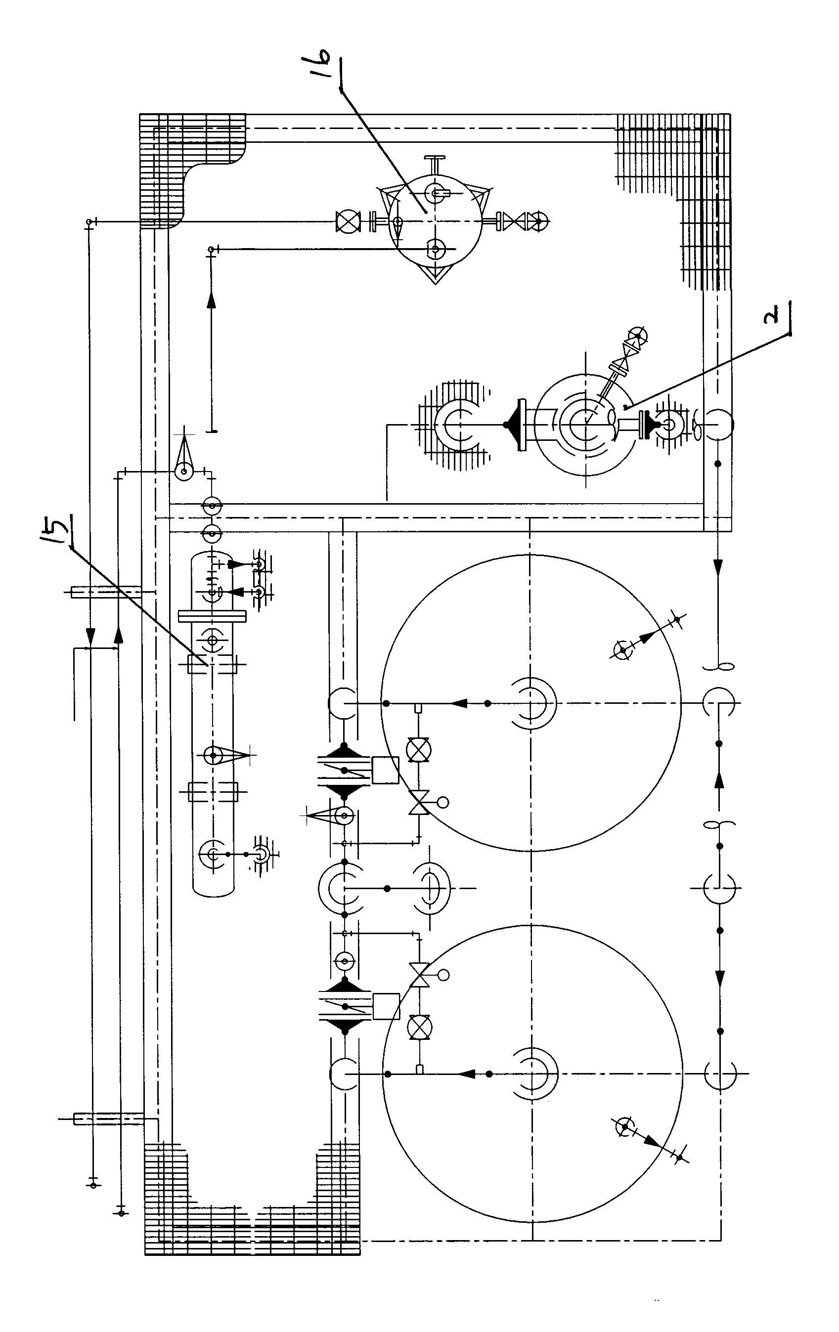
[0014] An integrated exhaust gas recovery device, which is provided with an integrated frame, and an oil gas recovery main pipe 1, a pressurized blower unit 21, a gas-liquid separator 2, an adsorption tower, a vacuum pump 14, a water-cooled heat exchanger 15, and a circulation system are arranged in the frame Refrigeration unit 16, recovery tank 18 and liquid discharge pump group 17, the adsorption tower is arranged at the front of the frame, the frame on one side of the adsorption tower is divided into upper and lower layers by side partitions, and the pressurized blower group is arranged at the side partition In the frame below the plate, the gas-liquid separator and circulating refrigeration unit are arranged on the upper part of the side partition, the frame at the rear of the adsorption tower is divided into upper and lower layers by the rear partition, and the vacuum pump, recovery tank and liquid drainage pump group are arranged In the frame below the rear bulkhead, a wa...


PUM


Abstract

Disclosed is an integrated exhaust gas recovery device. An oil gas recovery header pipe, a pressurized air-blower unit, a gas-liquid separation device, an adsorption tower, a vacuum pump, a heat exchanger, a cyclic refrigerating unit, a recovery pot, a hydraulic pump unit and a process pipeline are integrated into one body and are installed inside a special-purpose frame structure. Instrument andequipment installation and debugging are carried out before the device provided by the invention is out of the factory, thus realizing overall design, overall installation and overall debugging. After equipment arrives at the loading and unloading site, the device can be directly used only after connecting anchor bolts, the technical pipeline, power supply line and communication circuits and simple debugging, thus saving onsite design and onsite construction amount, shortening project duration, avoiding onsite welding, raising onsite security and simultaneously improving reliability of a handling control system.

Description

technical field [0001] The invention relates to an oil and gas transportation technology, in particular to a storage tank, tanker, oil tanker, tanker, tanker, etc. used for storage and unloading of gasoline or other volatile gases such as hydrocarbons and lipids. Integrated exhaust gas recovery unit. Background technique [0002] Petroleum and its products are mixtures of various hydrocarbons, the light components of which are highly volatile. In the process of oil extraction, refining, storage, transportation, sales and application, some of the lighter liquid components will inevitably be vaporized and discharged into the atmosphere, resulting in the loss of oil products and the pollution of the atmospheric environment, which has a greater impact hazards. [0003] According to the report of the 4th International Petroleum Conference, in the United Kingdom, during the whole process of oil products from refining and processing at the well site to product sales, the loss of ...

Claims


Application Information

Patent Timeline
Patent Type & Authority Patents(China)
IPC IPC(8): B01D53/02B01D53/14B01D5/00
Inventor 严振宇权小军孙兰萍韩会林王为周张兵
Owner 连云港远洋流体装卸设备有限公司
Why Eureka
Try Eureka