
Over-current quick-protection circuit for measurement instrument

A power analyzer and protection circuit technology, which is applied in the detection field, can solve problems such as endangering personal safety and damaging measuring instruments, and achieves the effects of fast protection action, strong overcurrent capability, and wide application range

Inactive Publication Date: 2014-03-26
BAODING TIANWEI XINYU TECH DEV
View PDF3 Cites 0 Cited by
  • Summary
  • Abstract
  • Description
  • Claims
  • Application Information

AI Technical Summary

Problems solved by technology

However, in some special occasions, the above-mentioned over-current protection circuit is no longer applicable. For example, during the transformer no-load and load tests, the current input terminal of the measuring instrument is connected to the secondary side of the external current transformer. If the above-mentioned over-current protection circuit is used, when the protection function When it takes effect, it is equivalent to opening the secondary side of the external current transformer, thereby generating high voltage on the secondary side of the external current transformer, which may damage the measuring instrument or even endanger personal safety

Method used


Image

  • Over-current quick-protection circuit for measurement instrument

Examples


Embodiment Construction

[0012] The present invention will be further described through the embodiments below in conjunction with the accompanying drawings.

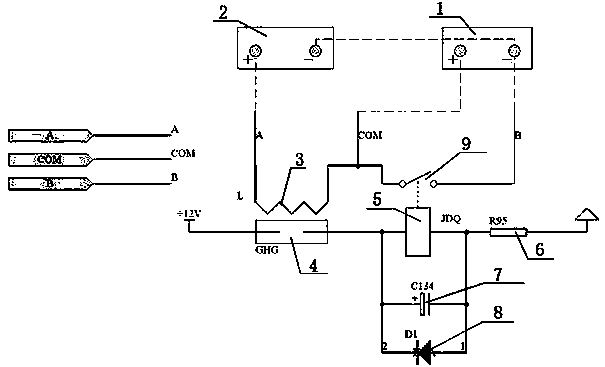
[0013] A fast overcurrent protection circuit for a power analyzer, comprising an input terminal 1 of a measuring instrument channel board, an input terminal 2 of a measuring instrument panel, an electromagnet 3, a dry reed switch and a relay. The electromagnet is an ironless electromagnet, dry The reed switch passes through the electromagnet coil, the normally open contact 4 of the reed switch is connected to the relay coil 5, the normally open contact 9 of the relay is connected to the input end of the channel board of the measuring instrument, and the input end of the measuring instrument panel is connected to the electromagnet ; Use ironless electromagnet and dry reed switch passing through the electromagnet coil to monitor whether the current input terminal of the measuring instrument is over-current.

[0014] When the protected current loop...


PUM


Abstract

The invention relates to an over-current quick-protection circuit for a power analyzer, and belongs to the technical field of detection. The technical scheme is that: an electromagnet (3) is a coreless electromagnet; a reed switch penetrates through a coil of the electromagnet; a normally open contact (4) of the reed switch is connected with a coil (5) of a relay; a normally open contact (9) of the relay is bridged at the input end of a channel plate of the measurement instrument; the input end (2) of a panel of the measurement instrument is connected with the electromagnet; and whether the current input end of the measurement instrument has over-current or not is monitored by the coreless electromagnet and the reed switch which penetrates through the coil of the electromagnet. Whether the current input end of the measurement instrument has the over-current or not is monitored by the coreless electromagnet and the reed switch which penetrates through the coil of the electromagnet, so that the over-current quick-protection circuit has the advantages of no influence on the input impedance of the measurement instrument and no undesirable impact on the measurement accuracy of the measurement instrument, can be used for quick protection over alternating over-current or direct over-current, is wide in application range, quick in protection and high in current conveyance capability, and can effectively prevent the damage of instantaneous high current to a channel circuit of the measurement instrument.

Description

technical field [0001] The invention relates to a fast overcurrent protection circuit for a power analyzer, which is suitable for the fast overcurrent protection circuit of the power analyzer and belongs to the technical field of detection. Background technique [0002] Generally speaking, measuring instruments use overcurrent protection circuits, mainly using devices such as fuses and relays. When the current in the circuit is too large, the protected circuit will be disconnected, thus playing the role of overcurrent protection. However, in some special occasions, the above-mentioned over-current protection circuit is no longer applicable. For example, during the transformer no-load and load tests, the current input terminal of the measuring instrument is connected to the secondary side of the external current transformer. If the above-mentioned over-current protection circuit is used, when the protection function When it takes effect, it is equivalent to opening the second...

Claims


Application Information

Patent Timeline
Patent Type & Authority Patents(China)
IPC IPC(8): H02H9/02G01R21/00
Inventor 何平刘大永陈志伟杜玉新路浩王永辉
Owner BAODING TIANWEI XINYU TECH DEV
Learn More