
Low-loss high-suppression minitype cavity body band-pass filter

A high-rejection, micro-cavity technology, applied in the field of filters, can solve the problems of large volume and insertion loss, and cannot be used in applications, and achieve the effects of high Q value, light weight, and simple circuit structure

Inactive Publication Date: 2012-06-20
WUXI NANLIGONG TECH DEV
View PDF2 Cites 10 Cited by
  • Summary
  • Abstract
  • Description
  • Claims
  • Application Information

AI Technical Summary

Problems solved by technology

Filters designed by conventional methods, such as hairpin filter structures, resonant cavity filter structures, and coaxial line filter structures, all have the disadvantages of large volume and insertion loss, and are often unusable for demanding applications

Method used


Image

  • Low-loss high-suppression minitype cavity body band-pass filter
  • Low-loss high-suppression minitype cavity body band-pass filter
  • Low-loss high-suppression minitype cavity body band-pass filter

Examples


Embodiment Construction

[0009] The present invention will be described in further detail below in conjunction with the accompanying drawings.

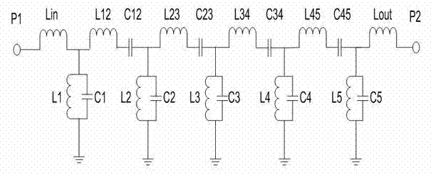
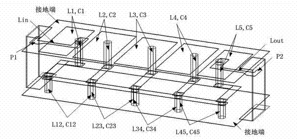
[0010] Combine figure 1 , The present invention is a low-loss and high-suppression micro-cavity bandpass filter, including a surface-mounted 50 ohm impedance input port P1, an input inductor Lin, a first-stage parallel resonance unit L1, C1, and a first electromagnetic coupling circuit L12, C12, the second-stage parallel resonant unit L2, C2, the second electromagnetic coupling circuit L23, C23, the third-stage parallel resonant unit L3, C3, the third electromagnetic coupling circuit L34, C34, the fourth-stage parallel resonant unit L4, C4, the fourth electromagnetic coupling circuit L45, C45, the fifth-level parallel resonant unit L5, C5, the output inductor Lout, the surface-mounted 50 ohm impedance output port P2 and the ground terminal; the first-level parallel resonant unit L1, C1 is composed of the first The inductor L1 and the first capacitor C1 are conne...


PUM


Abstract

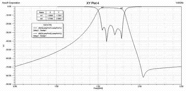
The invention relates to a low-loss high-suppression minitype cavity body band-pass filter which comprises 50 ohmic impedance input / output interfaces suitable for surface mounting, five parallel resonant units and input and output inductors, wherein the five parallel resonant units are realized by adopting a distributed parameter cylindrical cavity body coupling structure; and the 50 ohmic impedance input / output interfaces, the five parallel resonant units as well as the input and output inductors are realized by adopting a multilayer low-temperature co-fired ceramic technology. The low-loss high-suppression minitype cavity body band-pass filter provided by the invention has the advantages of good band-pass selectivity, good out-of-band suppression, lower insertion loss, small volume, light weight, high reliability, good electric property, good phase frequency characteristic linearity, good temperature stability, good electric property batch consistency, low cost, volume production and the like, and is especially suitable for wireless communication hand-held and portable terminal products of radars, correspondence, rocket carrying, aircraft carrying, missile carrying, spacecrafts, individual soldier mobile communication terminals and the like, as well as places and corresponding frequency band systems which have rigor requirements in volume, weight, electric property, reliability and the like.

Description

Technical field [0001] The invention relates to a filter, in particular to a micro-cavity band-pass filter with low loss and high suppression. Background technique [0002] With the development of microwave and millimeter wave communication, radar and other systems, especially in mobile handheld wireless communication terminals, individual satellite mobile communication terminals, military and civilian multi-mode multi-channel communication system terminals, airborne, missile-borne, and aerospace communication systems With the continuous miniaturization of microwave and millimeter wave communication modules, bandpass filters are the key electronic components in the corresponding waveband receiving and transmitting branches. Low loss and high stopband suppression microcavity microwave bandpass filters are an important development direction. . The main technical indicators describing the performance of this component are: passband operating frequency range, stopband frequency rang...

Claims


Application Information

Patent Timeline
Patent Type & Authority Applications(China)
IPC IPC(8): H01P1/207
Inventor 戴永胜左同生戚湧孙宏途汉敏尹洪浩李平谢秋月韩群飞冯媛
Owner WUXI NANLIGONG TECH DEV
Learn More