
Infrared imaging device based on network

An infrared thermal imager and infrared thermal imaging technology, applied in the directions of instruments, scientific instruments, measuring devices, etc., can solve the problems such as the inability to effectively use the optical fiber backbone network resources to remotely monitor the infrared thermal imager, and achieve all-round effective hidden dangers , Accurately identify and rigorously analyze, monitor the effect of hidden dangers

Inactive Publication Date: 2012-06-20
济南蓝动激光技术有限公司
View PDF3 Cites 7 Cited by
  • Summary
  • Abstract
  • Description
  • Claims
  • Application Information

AI Technical Summary

Problems solved by technology

[0004] The current infrared thermal imager in the coal mine collects data independently, and cannot effectively use the fiber optic backbone network resources to realize the remote monitoring infrared thermal imager

Method used


Image

  • Infrared imaging device based on network
  • Infrared imaging device based on network
  • Infrared imaging device based on network

Examples


Embodiment Construction

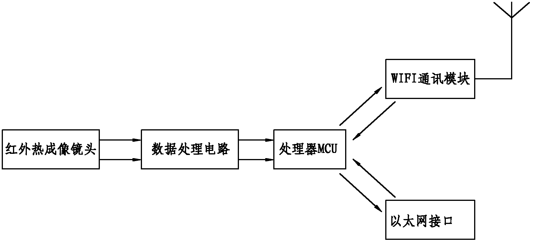
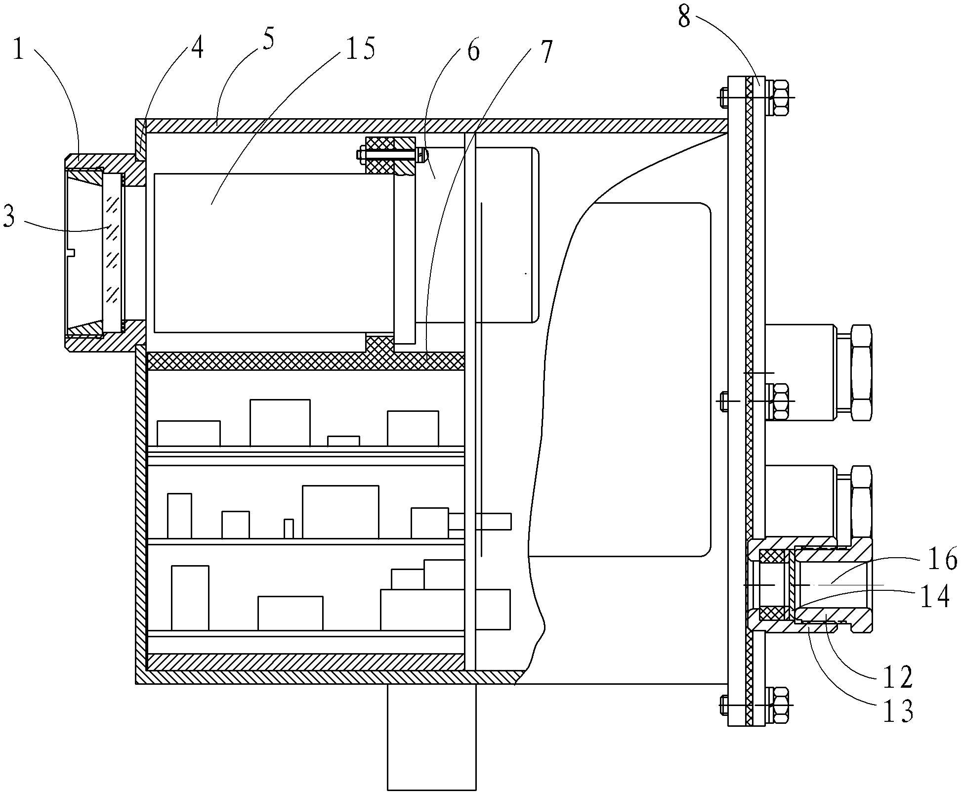
[0020] Such as figure 1 As shown, the network-based infrared thermal imager includes an infrared thermal imaging lens, a data processing circuit, a processor MCU, a WIFI communication circuit and an Ethernet interface.

[0021] The infrared thermal imaging lens is used to convert the detected heat into an electrical signal, that is, a temperature signal.

[0022] The data processing circuit processes the temperature signal collected by the infrared thermal imaging lens and converts it into a digital signal;

[0023] The processor MCU calculates the data of the data processing circuit, identifies the thermal field of the monitoring area, and then saves and transmits the data to the network through the WIFI communication circuit or the Ethernet interface;

[0024] The WIFI communication circuit is connected with the processor MCU, and is used to send the data processed by the processor MCU to the server computer in real time through the WIFI network;

[0025] The Ethernet inte...


PUM


Abstract

An infrared imaging device based on a network includes an infrared imaging lens, a data processing circuit, an MCU (Microprogrammed Control Unit) and an Internet interface; the infrared imaging lens is used for transforming detected heat into electrical signals, i.e. temperature signals; the data processing circuit is used for transforming the temperature signals into digital signals; and the MCU is used for processing the digital signals, calculating data simultaneously, distinguishing a thermal field in a monitoring zone, storing processed and calculated data, and transmitting the data to the network through the Internet interface. The infrared imaging device adopts the image network transmission technology, transmits real-time thermal field images to a present coal mine backbone network, and realizes remote dynamic monitoring.

Description

technical field [0001] The invention relates to the technical field of infrared thermal imagers, in particular to an infrared thermal imager for underground coal mines. Background technique [0002] Infrared is an electromagnetic wave that has the same nature as radio waves and visible light. It uses a special electronic device to convert the temperature distribution on the surface of an object into an image visible to the human eye, and displays the temperature distribution on the surface of the object in different colors or grayscales. It is called infrared thermal imaging technology. This electronic device is called Infrared thermal imager. [0003] In coal production, many equipment are often used in high temperature, high pressure and high-speed operation state. The application of infrared thermal imager to detect and monitor these equipment can not only ensure the safe operation of the equipment, but also detect abnormal conditions, so as to eliminate hidden dangers i...

Claims


Application Information

Patent Timeline
Patent Type & Authority Applications(China)
IPC IPC(8): G01J5/00
Inventor 程绍澜李天池张文亮
Owner 济南蓝动激光技术有限公司
Learn More