
Method for accurately detecting position of low-speed small unmanned aerial vehicle through radar photoelectric cooperation

An unmanned aerial vehicle, low-slow and small technology, applied in the field of unmanned aerial vehicle detection, can solve the problem of low positioning accuracy of unmanned aerial vehicles, and achieve the effect of good maneuverability, reduced error and high precision

Active Publication Date: 2021-04-02
CHENGDU JINJIANG ELECTRONICS SYST ENG
View PDF21 Cites 2 Cited by
  • Summary
  • Abstract
  • Description
  • Claims
  • Application Information

AI Technical Summary

Problems solved by technology

[0003] The purpose of the present invention is to overcome the deficiencies of the prior art, to provide a radar photoelectric cooperative method for accurately detecting the position of low-speed and small unmanned aerial vehicles, and to solve the problems in the existing technology due to the complexity of the urban environment and the special characteristics of low-altitude, slow-speed and small targets. The technical problem of low positioning accuracy of unmanned aerial vehicles due to the performance limitation of single radar or optoelectronic equipment

Method used


Image

  • Method for accurately detecting position of low-speed small unmanned aerial vehicle through radar photoelectric cooperation
  • Method for accurately detecting position of low-speed small unmanned aerial vehicle through radar photoelectric cooperation
  • Method for accurately detecting position of low-speed small unmanned aerial vehicle through radar photoelectric cooperation

Examples


Embodiment 1

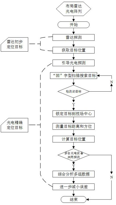
[0040] Such as figure 1 As shown, the radar-optical collaborative method for accurately detecting the position of "low, slow and small" unmanned aerial vehicles includes the following steps:

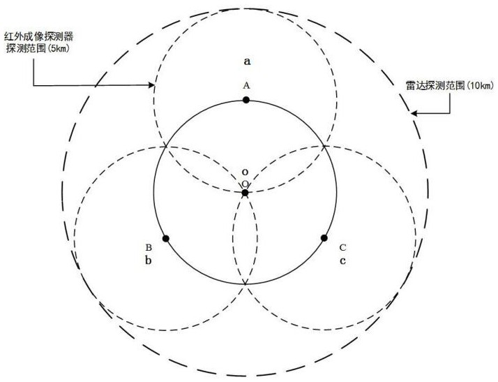
[0041] Step S1. Combining the detection performance and detection methods of radar and photoelectric equipment, arrange them in a certain array on urban high-rise buildings, so as to realize the monitoring of large-scale urban areas.

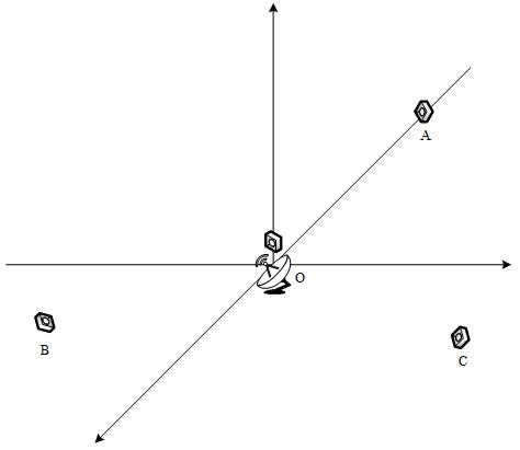
[0042] Step S2. Establish a cooperative detection space Cartesian coordinate system, use radar to initially detect the position of the UAV in the urban building complex, and select the corresponding photoelectric device for subsequent operations according to the position.

[0043]Step S3. According to the target position information detected by the radar, adjust the observation direction and angle of the photoelectric equipment so that the staring field of view is near the target, and then scan and search and capture the target.

[0044] Step S4. After ca...


PUM


Abstract

The invention relates to a method for accurately detecting the position of a low-speed small unmanned aerial vehicle through radar photoelectric cooperation, and the method comprises the steps: enabling one radar and a plurality of photoelectric equipment to be installed at a commanding height of a monitoring region in an array layout mode, building a cooperative detection space rectangular coordinate system through taking the center of an array as an original point, and preliminarily detecting the position of the unmanned aerial vehicle through the radar, according to the target position information detected by the radar, adjusting the observation direction and angle of the corresponding photoelectric equipment so that the staring field is located near the target, then carrying out scanning search, and capturing the target; after the target is captured, tracking the target, locking the target to the center of a field of view, and calculating the position of the target in a cooperativedetection space rectangular coordinate system according to the distance, the direction angle and the pitch angle between the target and the photoelectric equipment. According to the scheme, the technical problem of low positioning precision of the unmanned aerial vehicle due to the complexity of an urban environment, the particularity of a low-altitude low-speed small target and the performance limitation of independent radar or photoelectric equipment in the prior art is solved.

Description

technical field [0001] The invention relates to the field of detection of unmanned aerial vehicles, in particular to a method for accurately detecting the position of low-speed and small unmanned aerial vehicles through radar and photoelectric cooperation. Background technique [0002] The frequent occurrence of "low, slow and small" unmanned aerial vehicles, such as random flying and black flying, has brought new challenges to urban security work. Intercepting and attacking such targets requires precise positioning of the target first, and due to the complexity of the urban environment and the particularity of low-altitude, slow-moving and small targets, it is difficult to accurately detect the position of such unmanned aerial vehicles. Although radar can detect "low, slow and small" unmanned aerial vehicles, it is not stable enough, and the positioning accuracy is poor, and the error can reach several meters or even tens of meters. The detection angle of photoelectric equ...

Claims


Application Information

Patent Timeline
Patent Type & Authority Applications(China)
IPC IPC(8): G01S13/66G01S13/86G01S13/42G01J5/00
CPCG01S13/66G01S13/42G01S13/865G01S13/86G01J5/00G01J2005/0077
Inventor 董帅徐晓天马小莉刘丽
Owner CHENGDU JINJIANG ELECTRONICS SYST ENG
Learn More