Jet type condenser

A technology of jet condenser and water chamber, which is applied in the field of exhaust steam cooling system, can solve the problems of increasing the load of the air extraction pump, increasing the pressure of the condenser, and affecting the performance of the condenser, so as to reduce the degree of supercooling, The effect of reducing heat consumption and facilitating large-scale promotion and use

Active Publication Date: 2012-06-20
DONGFANG TURBINE CO LTD
View PDF3 Cites 7 Cited by
  • Summary
  • Abstract
  • Description
  • Claims
  • Application Information

AI Technical Summary

Problems solved by technology

However, these two adjustments have the following defects: if the method (1) is adopted, only the lower inner water chamber 4 is used for film spraying. determined by the water pressure
However, if only the lower inner water chamber 4 is used in winter working conditions, since the flow cross section of the water guide pipe 16 is determined and unchanged, if the water pressure of the lower inner water chamber 4 meets the film-forming effect requirements of the nozzle 1, then enter the air-cooled The amount of cooling water in zone 6 is far greater than 5% of the total cooling water entering the condenser, so that a large amount of cooling water enters the air-cooling zone 6, and this part of cooling water cannot be completely heated to saturated water, thus affecting the performance of the condenser
If method (2) is adopted, only the upper inner water chamber 3 is used for film spraying, at this time no cooling water enters the lower inner water chamber 4, and no cooling water enters the air-cooling zone 6, so that the steam in the air-cooling zone 6 cannot be further condensed , increasing the load of the air extraction pump will lead to an increase in the pressure of the condenser and affect the performance of the steam turbine
Therefore, the adjustment of the cooling water system can only make the valves 17 and 18 normally open. By adjusting the valves 17 and 18, the pressure of the upper inner water chamber 3 and the lower inner water chamber 4 is controlled. The pressure of the inner water chamber 3 and the lower inner water chamber 4 is lower than the design working condition, and the film-forming effect of the nozzles in each water chamber becomes worse, and the film-forming effect cannot be guaranteed
Therefore, in winter working conditions, this adjustment cannot improve the pressure of the upper inner water chamber 3 and the lower inner water chamber 4, so that the design of the multi-layer inner water chamber is on the surface, and the condensation effect of the condenser cannot be guaranteed.

Method used


Image

  • Jet type condenser
  • Jet type condenser
  • Jet type condenser

Examples


Embodiment 1

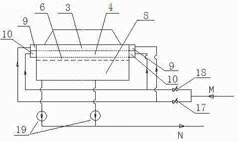
[0040] Such as Figure 6 As shown, it is a schematic diagram of the first cooling water system of the multi-layer inner water chamber jet condenser cooling water system of the present invention. It is equipped with a set of power equipment, that is, equipped with a cooling water pump 15 and a water turbine 14. The system is generally a multi-layer inner water chamber spray condenser cooling water system for small units. The cooling water system only includes a circulating water pump 15, a water turbine 14, a cooling tower, a condenser and the pipelines and flow regulating elements between them, forming a circulating loop. The pipeline at the rear end of the turbine 14 is divided into three branch pipes X, Y and Z on one side to enter the condenser, wherein the water inlet pipe X of the upper outer water chamber enters the upper outer water chamber 9, and the upper chamber water inlet pipe Y of the lower outer water chamber Enter the upper cavity 10-1 of the lower outer water ...

Embodiment 2

[0043] Such as Figure 7 As shown, it is a schematic diagram of the second structural form of the multi-layer inner water chamber jet condenser cooling water system of the present invention, which is generally a multi-layer inner water chamber jet condenser cooling water system of a medium-sized unit. The system includes two sets of power equipment, that is, two parallel circulating water pumps 15-1, 15-2 and two parallel water turbines 14-1, 14-2. That is to say, there are two water turbines 14-1 and 14-2 connected in parallel on the cooling water input pipeline M to coordinately control the cooling water volume and work capacity, and two circulating water pumps 15-1 and 15-1 are connected in parallel on the circulating water output pipeline N. 15-2, while pumping circulating water into the cooling tower.

[0044] In this embodiment, the pipelines at the rear ends of the turbines 14-1 and 14-2 are divided into six branch pipes to enter the condenser, wherein the water inlet ...

Embodiment 3

[0048] As shown in Figure 8, it is a schematic diagram of the third structural form of the multi-layer inner water chamber jet condenser cooling water system of the present invention, which is generally a multi-layer inner water chamber jet condenser cooling water system of a large unit. The cooling water system only includes three sets of power equipment, that is, three parallel circulating water pumps 15-1, 15-2, 15-3 and three parallel water turbines 14-1, 14-2, 14-3. That is to say, three water turbines 14-1, 14-2, and 14-3 are connected in parallel on the cooling water input pipeline M to coordinately control the cooling water volume and work capacity, and three circulating water pumps 15-1 are connected in parallel on the circulating water output pipeline N. 1, 15-2, 15-3, pump circulating water into the cooling tower at the same time.

[0049] In this embodiment, the design of the pipelines at the rear ends of the water turbines 14-1, 14-2 and 14-3 is the same as that o...


PUM


Abstract

The invention provides a jet type condenser, which comprises a shell. A plurality of multilayered inner water chambers are arranged in the shell, multilayered outer water chambers which are correspondingly communicated with the inner water chambers are arranged outside the shell, each outer water chamber is communicated with a water source, the lower portion of the inner water chamber in a bottomlayer is an air-cooling area, and a water guiding tube which is communicated with the air-cooling area is arranged at the bottom of the inner water chamber of the bottom layer. The jet type condenseris characterized in that a transverse partition board is disposed in the inner water chamber of the bottom layer, the inner space of the inner water chamber of the bottom layer is divided into an upper cavity and a lower cavity which are independent, and correspondingly, the outer water chamber which corresponds to the inner water chamber of the bottom layer is also divided into two independent cavities which are respectively communicated with the two cavities of the inner water chamber of the bottom layer and respectively connected with the water source. The service range of the jet type condenser is expanded, when circulation water quantity is reduced in various seasons, jetting press heads of each row of sprayers can be guaranteed in the best range, the water quantity of the air-cooling area is guaranteed to be 5% of the total quantity of cooling water entering the jet type condenser under the work condition, condenser depression of condensate of the condenser can be remarkably reduced, running thermal consumption of a unit is reduced, and the jet type condenser is simple and feasible, and is convenient for large-scale popularization and use.

Description

technical field [0001] The invention relates to an exhaust steam cooling system of an air-cooling unit of a thermal power station, in particular to a jet condenser, which has a multi-layer inner water chamber structure and a special adjustment method. Background technique [0002] In the 1930s, with the rapid development of industry, industrial water consumption increased significantly, and there was a shortage of water. Oil refineries and petrochemical plants gradually replaced water coolers with air coolers. Later, air cooling systems began to be used in the power station industry. The air-cooling system of the power station is divided into direct air-cooling system and indirect air-cooling system, and the indirect air-cooling system is divided into indirect air-cooling system using jet condenser and indirect air-cooling system using surface condenser. Since the cooling water of the surface condenser needs to exchange heat with the steam in the tube, there is an end differ...

Claims


Application Information

Patent Timeline
Patent Type & Authority Applications(China)
IPC IPC(8): F28B3/04F28B9/00
CPCF28B5/00F28B1/02F28B3/04B01D5/0027
Inventor 徐梅许晔刘伟龙谭顺科
Owner DONGFANG TURBINE CO LTD
Why Eureka
Try Eureka