
Fuel and air mixing device for low-pollution burning chamber of gas turbine

A gas turbine and mixing device technology, applied in the combustion chamber, continuous combustion chamber, combustion method, etc., to achieve the effects of widening the stable working range, strengthening the interaction, and increasing the relative axial speed

Active Publication Date: 2013-10-09
INST OF ENGINEERING THERMOPHYSICS - CHINESE ACAD OF SCI
View PDF6 Cites 0 Cited by
  • Summary
  • Abstract
  • Description
  • Claims
  • Application Information

AI Technical Summary

Problems solved by technology

[0006] The technical problem to be solved by the present invention is: in order to overcome the shortcomings and deficiencies of the above-mentioned prior art, the present invention adopts the scheme of fuel classification to realize the It can stabilize combustion and effectively reduce pollutant emissions, especially NOx emissions under heavy working conditions; at the same time, it can control the penetration depth of fuel jet, strengthen the atomization and mixing of air to fuel jet, and effectively suppress fuel jet Coking and flashback problems caused by impingement on cyclone channel walls

Method used


Image

  • Fuel and air mixing device for low-pollution burning chamber of gas turbine
  • Fuel and air mixing device for low-pollution burning chamber of gas turbine
  • Fuel and air mixing device for low-pollution burning chamber of gas turbine

Examples


Embodiment Construction

[0029] In order to make the object, technical solution and advantages of the present invention clearer, the invention will be further described in detail below with reference to the accompanying drawings and examples.

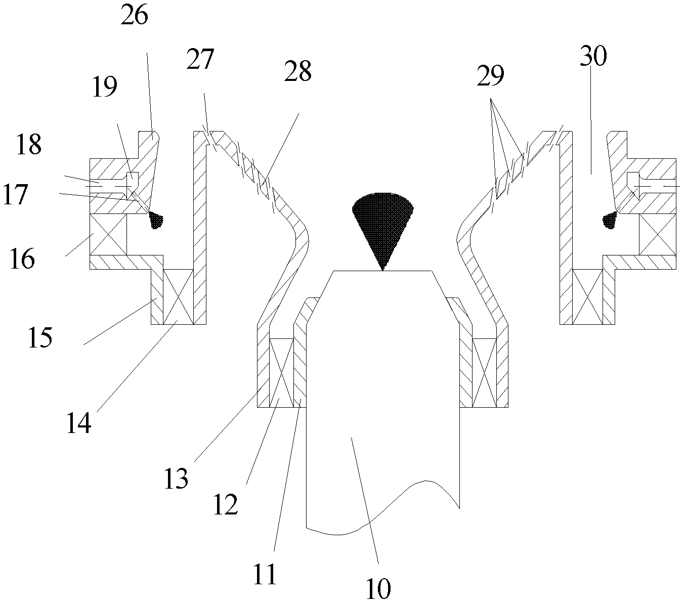
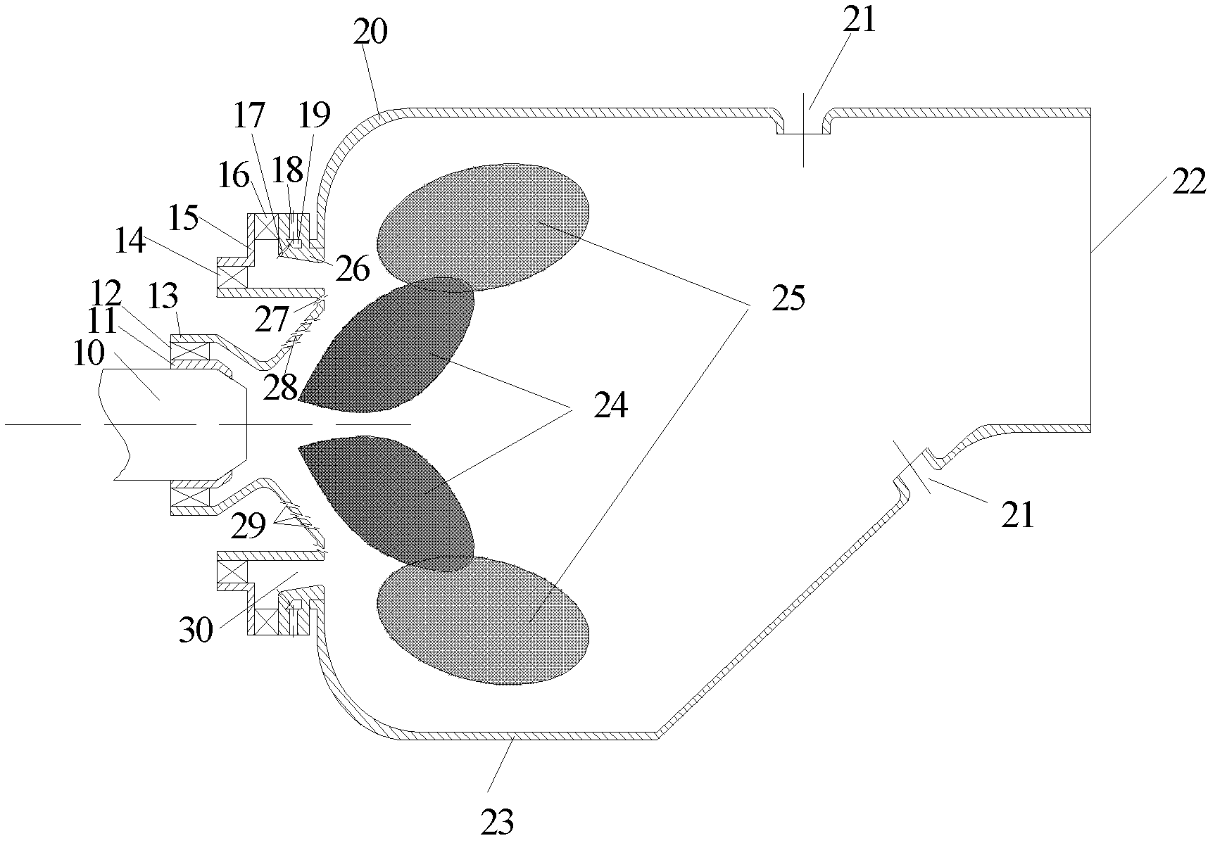
[0030] figure 1 It is a cross-sectional view of the structure of the fuel and air mixing device used in the low-pollution combustion chamber of a gas turbine. It adopts the scheme of staged fuel supply, including the main combustion stage and the duty stage. The duty stage includes a centrifugal atomizing nozzle 10, a first-stage axial air Cyclone 12 and conical flame stabilizer 28, wherein, centrifugal atomizing nozzle 10 is positioned at the center of described device, and primary axial air swirler 12 is arranged on the outer ring of centrifugal atomizing nozzle 10, conical The flame stabilizer 28 is located behind the centrifugal atomizing nozzle 10. The fuel on duty is sprayed through the centrifugal atomizing nozzle 10 for primary atomization, and then se...


PUM


Abstract

The invention discloses a fuel and air mixing device for a low-pollution burning chamber of a gas turbine. Fuel comprises a main burning level and a duty burning level; and air is supplied by a three-stage cyclone. The fuel and air mixing device is characterized in that the central duty level adopts diffusive burning, and the peripheral main burning level adopts premixing or semi-premixing burning. The central duty level consists of a centrifugal atomizing nozzle and first-stage cyclone air; and the rotating directions of the first-stage cyclone air and second-stage cyclone air are opposite. The fuel of the main burning level is supplied by a multipoint direct-injection type nozzle, the air is respectively supplied by the second-stage cyclone air and third-stage cyclone air, and the rotating directions of the second-stage cyclone air and third-stage cyclone air are opposite. The central duty level is used when in low working conditions such as starting and slowing and the like, so that the stable burning range can be widened, the burning efficiency can be improved and the emission of CO and UHC is reduced; and when in large working conditions, the duty level and the main burning level work simultaneously, the duty level provides a stable ignition source for the main burning level, a main burning area is in a lean-oil state, and the temperature is far lower than the temperature of insulated flame, so that the emission of NOx under the large working conditions can be obviously reduced. The fuel and air mixing device can be used for an aerial gas turbine engine or an industrial gas turbine.

Description

technical field [0001] The invention relates to a fuel oil and air mixing device of a low-pollution combustion chamber, in particular to a fuel oil and air mixing device which utilizes a fuel oil classification scheme to realize low pollution emission of a gas turbine. Background technique [0002] For gas turbine engines using liquid fuels, fuel atomization and mixing have a decisive impact on engine combustion performance, combustion efficiency and pollutant emissions. Therefore, research on fuel atomization has received attention, which has also promoted the development of fuel atomization nozzles. [0003] The International Civil Aviation Organization's pollutant emission standards for aviation gas turbines are becoming more and more stringent, especially for NOx pollution emission requirements. Low-pollution combustion has become the development trend of modern aero-engine combustors. Currently proposed low-pollution combustion technologies include rich combustion-quenc...

Claims


Application Information

Patent Timeline
Patent Type & Authority Patents(China)
IPC IPC(8): F23R3/04F23R3/26F23R3/42
Inventor 刘存喜毛艳辉刘富强杨金虎徐纲
Owner INST OF ENGINEERING THERMOPHYSICS - CHINESE ACAD OF SCI
Learn More