Mechanical winch automatic reversing cable distributor mechanism

A technology of automatic reversing and cable puller, which is applied in the direction of clockwork mechanism and hoisting device, which can solve the problems of double-threaded screw type jamming and complicated system, and achieve the effect of compact mechanism

Inactive Publication Date: 2012-06-20
HARBIN ENG UNIV
View PDF7 Cites 10 Cited by
  • Summary
  • Abstract
  • Description
  • Claims
  • Application Information

AI Technical Summary

Problems solved by technology

[0003] At present, most cable-discharging mechanisms use a screw to drive a cable guide, and the screw is driven by an electric motor or a hydraulic motor. The closed-loop control technology is adopted. The advantage is that the cable-discharging density can be quickly adjusted according to the diameter of the cable. However, when it comes to control technology, the system is relatively complex. Complicated, such as the "winch flexible automatic cable discharge device" recorded in the patent document with application number 200610125490.3, etc.
The mechanical cable unwinder has transmission forms such as double-threaded screw type or chain type. It can automatically unwind cables without a control system, but it can only unwind cables at a fixed density, and the double-threaded screw type is prone to jamming, such as the application number It is the "two-way screw type cable unwinder" recorded in the patent document of 201020119935.9, which has made technical improvements specifically for the lubrication of the screw rod

Method used


Image

  • Mechanical winch automatic reversing cable distributor mechanism
  • Mechanical winch automatic reversing cable distributor mechanism
  • Mechanical winch automatic reversing cable distributor mechanism

Examples


Embodiment Construction

[0022] The present invention is described in more detail below in conjunction with accompanying drawing example:

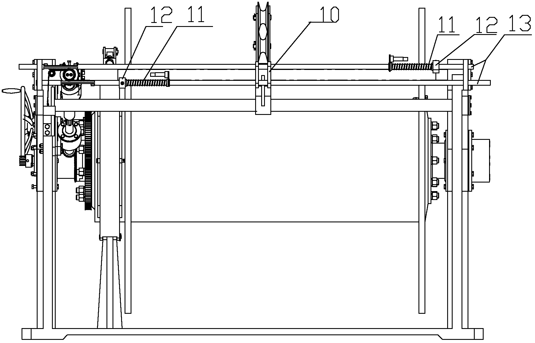
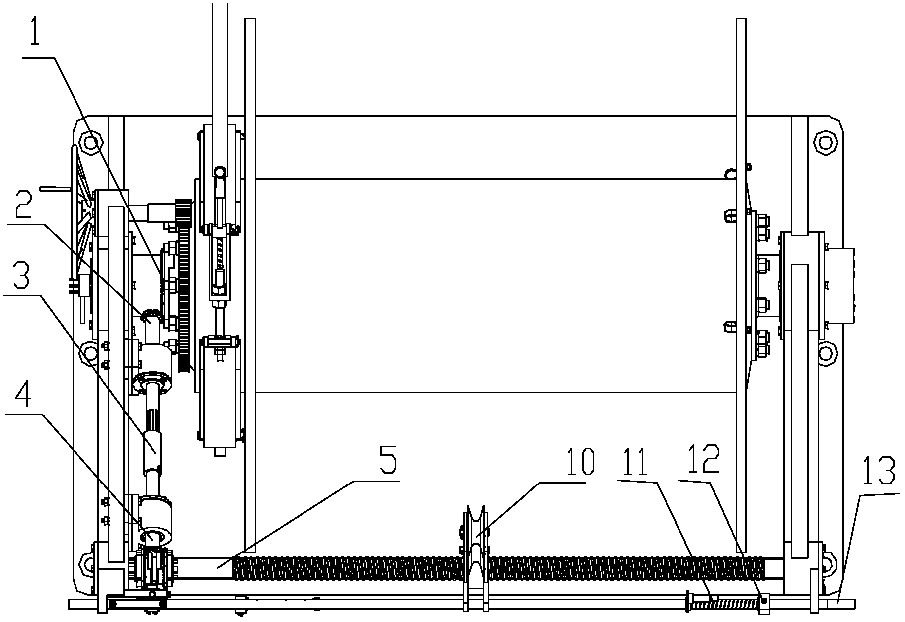
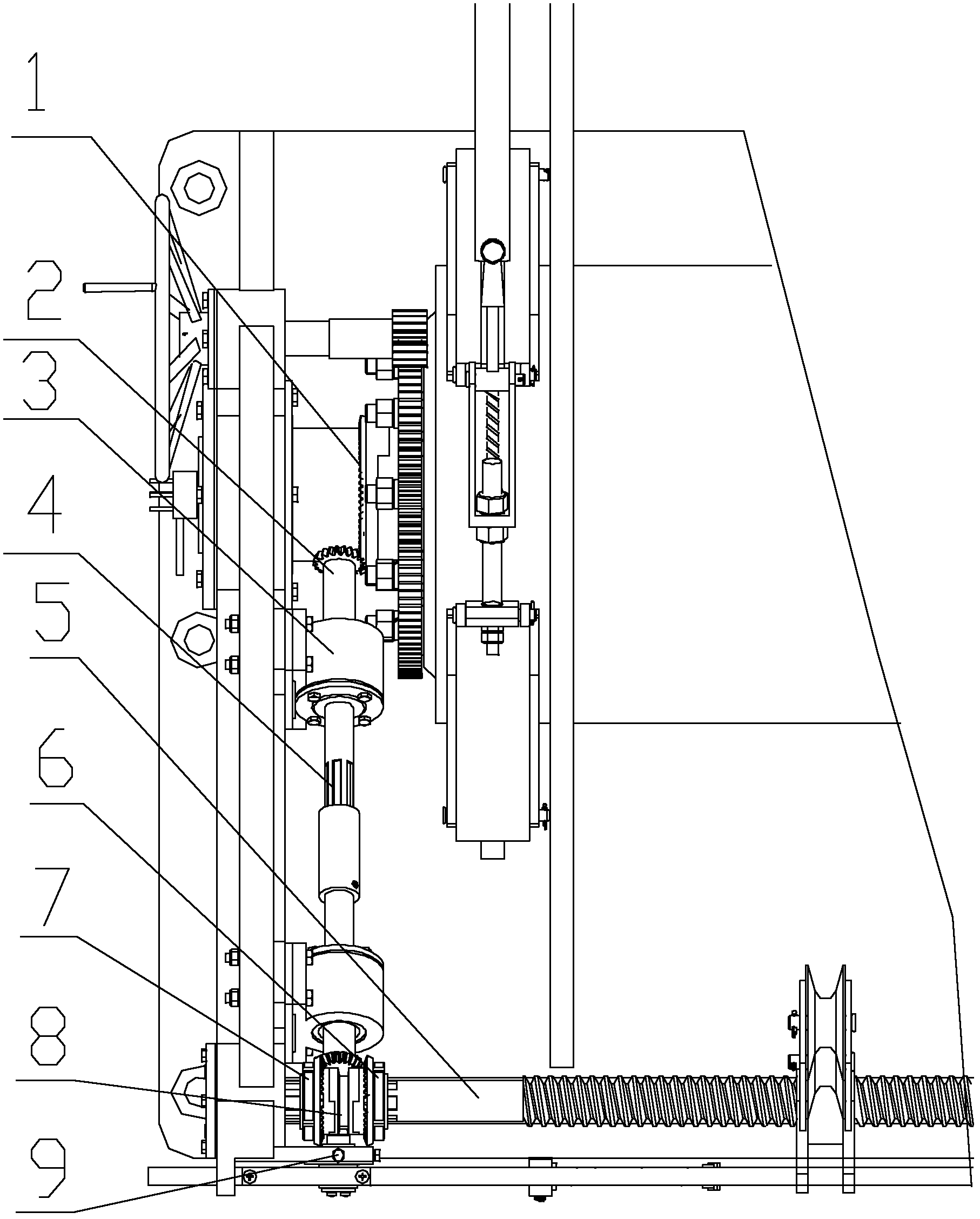
[0023] combine figure 1 and figure 2 , the first bevel gear 1 meshes with the first bevel gear shaft 2, the first bevel gear shaft 2 and the second bevel gear shaft 4 are connected through a coupling 3, the second bevel gear shaft 4 is connected with the second bevel gear 6 and the second bevel gear shaft The reversing bevel gear set composed of three bevel gears 7 (such as image 3 shown) meshes with one of the bevel gears. The rotation of the first bevel gear 1 will drive a bevel gear in the reversing bevel gear set to rotate, thereby driving the leading screw 5 to rotate. Simultaneously combine image 3 , the reversing bevel gear set consists of two identical oppositely mounted bevel gears.

[0024] The fairlead 10 is embedded with a nut, which can reciprocate along the axial direction of the leading screw under the drive of the leading screw 5; the pull ...


PUM


Abstract

The invention provides a mechanical winch automatic reversing cable distributor mechanism, which comprises a motive power transmitting mechanism, a reversing bevel gear group, a cable guide mechanism and a reversing trigger mechanism, wherein a first bevel gear is arranged on a rotating shaft of a winch, the motive power transmitting mechanism is formed by connecting two bevel gear shafts througha shaft coupler, the reversing bevel gear group consists of a second bevel gear and a third bevel gear which are arranged at splines of inner and outer ring belt teeth arranged at the end part of a screw rod, the end part of one bevel gear shaft of the motive power transmitting mechanism is engaged with the first bevel gear, the end part of the other bevel gear shaft of the motive power transmitting mechanism is positioned between the second bevel gear and the third bevel gear and is engaged with one of the second bevel gear and the third bevel gear, the cable guide mechanism comprises a screw lead and a cable guide frame sheathed on the screw rod through a screw nut, the reversing trigger mechanism comprises two pull rods passing through the cable guide frame, the end part of each pull rod is provided with a spring, a position limiting block and racks, and a ratchet mechanism used for shifting the second bevel gear or the third bevel gear is arranged between the two racks. The structure of the whole mechanism is compact and ingenious, and the automation degree is high.

Description

technical field [0001] The invention relates to a mechanical cable-discharging mechanism, in particular to a cable-discharging mechanism of an umbilical cable winch. Background technique [0002] During the use of various underwater robots, especially the underwater use of ROV (underwater robot), there is usually an umbilical winch to store or release the umbilical cable, so that the underwater robot can move freely underwater without Impairment of movement caused by excessive or insufficient length of the umbilical cord. The length of the umbilical cable to be stored in the umbilical winch must meet the voyage needs of the underwater robot. At present, the length of the umbilical cable required by the underwater robot ranges from several hundred to thousands of meters, that is, the winch drum must be wound with multiple layers of umbilical cables, so it is very necessary A cable-discharging mechanism is provided for the winch so that the umbilical cable is regularly wound ...

Claims


Application Information

Patent Timeline
Patent Type & Authority Applications(China)
IPC IPC(8): B66D1/38
Inventor 王玉甲张天弛王超张波杨超
Owner HARBIN ENG UNIV
Why Eureka
Try Eureka