
Micro-water-column guiding laser micromachining device

A micro-machining and laser technology, applied in laser welding equipment, metal processing equipment, manufacturing tools, etc., to achieve the effects of small heat-affected zone, low cost, and small processing stress

Inactive Publication Date: 2012-06-20
CHONGQING CHANGAN AUTOMOBILE CO LTD
View PDF6 Cites 17 Cited by
  • Summary
  • Abstract
  • Description
  • Claims
  • Application Information

AI Technical Summary

Problems solved by technology

[0004] The purpose of the present invention is to provide a micro-water column guided laser micromachining method and device with simple structure and reliable operation, so as to solve the coupling adjustment problem between the focused laser and the water beam optical fiber

Method used


Image

  • Micro-water-column guiding laser micromachining device
  • Micro-water-column guiding laser micromachining device

Examples


Embodiment Construction

[0014] Further illustrate structure of the present invention below in conjunction with accompanying drawing:

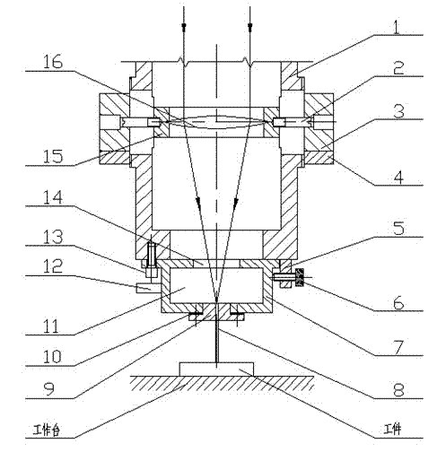
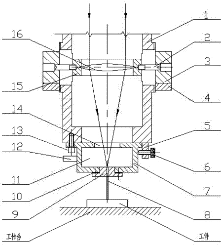
[0015] Such as figure 1 As shown, the micro-water column guided laser micromachining device includes a support sleeve 1, a water tank 7, a nozzle 9, an optical focus lens 16, etc., an optical focus lens 16 is horizontally installed in the support sleeve 1, and the optical focus lens 16 and the The nozzle hole center adjustment mechanism in the Z direction is connected. A water tank 7 is installed at the lower port of the support sleeve 1, and the water tank is connected to a pressurized water source through a water inlet joint 12. The center of the top of the water tank 7 is a quartz window 14, facing the center of the lower port of the support sleeve 1, the center of the bottom of the water tank 7 is provided with a nozzle 9, and the focal point of the optical focusing lens 16 just falls on the micropore center of the nozzle. The water tank 7 is also connected with...


PUM


Abstract

The invention relates to a micro-water-column guiding laser micromachining device, which comprises a supporting sleeve, a water tank, a nozzle and an optical focusing lens. The optical focusing lens is mounted in the supporting sleeve horizontally through a lens mount, and the lens mount is connected with a nozzle orifice center regulating mechanism in the Z direction. The water tank is mounted at the lower end opening of the supporting sleeve, and is connected with a high-pressure water system through a water inlet pipe joint. A quartz window is arranged in the middle of the top end of the water tank and faces the center of the lower end opening of the supporting sleeve, the nozzle is arranged in the middle of the bottom end of the water tank, and the focusing point of the optical focusing lens is located at the orifice center of the nozzle. The water tank is also connected with nozzle orifice center regulating mechanisms in the horizontal X direction and the Y direction. The micro-water-column guiding laser micromachining device is provided with the regulating mechanisms for coupling alignment of laser in the horizontal direction and the longitudinal direction, and accordingly three-dimension relative positions of the laser focal spot and the nozzle orifice center can be regulated accurately, and coupling effect of the focusing lens and optical fibers in water stream during water guiding laser micromachining is guaranteed.

Description

technical field [0001] The invention belongs to the technical field of precision machining, and in particular relates to a laser micromachining method and device. Background technique [0002] With the continuous development of precision and ultra-precision processing technology, the combination of laser and other processing technologies has gradually become the mainstream technology in the field of processing and manufacturing. The micro-water guide laser processing technology guides the focused laser beam of a specific wavelength into the high-speed flowing water beam as an optical fiber. After the laser undergoes multiple total reflections at the interface between water and air, it forms a high-energy beam and shoots to the surface of the workpiece to realize the fine-tuning of the workpiece. processing. Compared with the traditional laser micromachining technology: ZL02138076.7 laser composite treatment method for the surface of friction pair; application number 2006100...

Claims


Application Information

Patent Timeline
IPC IPC(8): B23K26/36B23K26/14B23K26/42B23K26/04B23K26/146
Inventor 华希俊张培耘倪健符永宏尹必峰王匀余长东张云平
Owner CHONGQING CHANGAN AUTOMOBILE CO LTD
Learn More