
Matching design method for control system and imaging system

A technology of imaging system and control system, which is applied in the direction of control, measuring device and instrument using feedback, which can solve the problems of the decrease of spatial resolution of imaging system and so on.

Inactive Publication Date: 2012-06-13
INST OF OPTICS & ELECTRONICS - CHINESE ACAD OF SCI
View PDF7 Cites 2 Cited by
  • Summary
  • Abstract
  • Description
  • Claims
  • Application Information

AI Technical Summary

Problems solved by technology

D.Wulich, M.S.Kopeika pointed out in the article "Image resolution limits resulting from mechanical vibrations" (Opt.Eng, 26, 529-533) that the relative motion between the target and the sensor caused by vibration will lead to a decrease in the spatial resolution of the imaging system

Method used


Image

  • Matching design method for control system and imaging system
  • Matching design method for control system and imaging system
  • Matching design method for control system and imaging system

Examples


Embodiment Construction

[0049] The present invention will be described in detail below in conjunction with the accompanying drawings and specific embodiments.

[0050] Such as Figure 4 The design process shown is applicable to the azimuth system and pitch system of the photoelectric tracking and measuring equipment. The azimuth system is taken as an example to introduce the specific implementation:

[0051] (1) According to the motion characteristics of the tracked measurement target, the maximum angular velocity of the target relative to the azimuth axis of the photoelectric tracking measurement equipment during the measurement process can be determined and maximum angular acceleration Then the equivalent sinusoidal signal of the target in the azimuth direction is obtained:

[0052] θ e (t) = θ max sin(w e t)

[0053] θ max = ( θ max v ...


PUM


Abstract

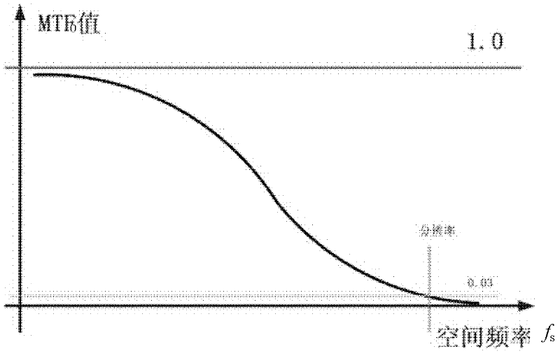
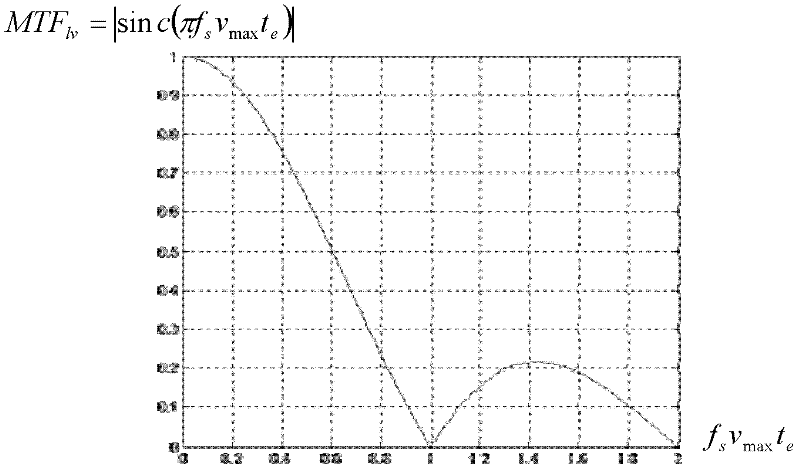
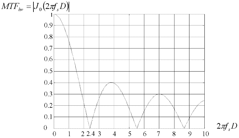
The invention discloses a matching design method for a control system and an imaging system. In the method, a target signal is equivalent to a sine input signal and is partitioned into a low-frequency target and a high-frequency target according to the period of an equivalent sine signal and the exposure time te of the imaging system; the influence factors (MTFv) of the lower-frequency target and low-frequency target on the dynamic space resolution of photoelectric tracing equipment have different functional forms MTF1v and MTFhv; the product of the MTFv and a modulation transfer function MTF0 of the imaging system under a static condition is a modulation transfer function MTF of the photoelectric tracing measuring equipment in a working state; and space resolution fs0 of the equipment in the working state can be obtained by using the MTF; and by adjusting the magnitudes of the MTFv and the MTF0, the balance between design difficulties of the control system and the imaging system is realized.

Description

technical field [0001] The invention relates to a matching design method suitable for photoelectric tracking and measuring equipment, specifically, optimizing the design of the optical-mechanical structure, control system and imaging system of the photoelectric tracking and measuring equipment. Background technique [0002] Photoelectric tracking measurement equipment is a large-scale equipment for high-precision measurement. The spatial resolution of the equipment, especially the spatial resolution in the working process, directly determines the tracking measurement performance of the entire system. At present, the development of photoelectric tracking and measurement equipment often regards the spatial resolution under static conditions and the control accuracy of the control system as two relatively independent development indicators. In fact, the dynamics, that is, the spatial resolution in the working process, can better reflect the performance of the photoelectric trac...

Claims


Application Information

Patent Timeline
Patent Type & Authority Applications(China)
IPC IPC(8): G01C25/00G05D3/12
Inventor 刘兴法邹华杜俊峰刘儒贞包启亮
Owner INST OF OPTICS & ELECTRONICS - CHINESE ACAD OF SCI
Learn More