
Undercarriage buffer

A landing gear buffer, landing gear technology, applied in the direction of landing gear, shock absorber, shock absorber, etc., can solve the problems of increasing the structural weight of the landing gear buffer, making it out, and the performance of the buffer cannot be fully exerted.

Active Publication Date: 2012-06-13
NANJING UNIV OF AERONAUTICS & ASTRONAUTICS
View PDF4 Cites 9 Cited by
  • Summary
  • Abstract
  • Description
  • Claims
  • Application Information

AI Technical Summary

Problems solved by technology

The problem is that when the shock absorber is close to the maximum compression state, due to the very weak elasticity, it is often difficult to find a suitable maximum dynamic compression load point for the expected design result, and make the maximum stroke and maximum dynamic compression load meet the specific requirements at the same time. The design requirements of the structure and the maximum (limit) load factor, so it cannot provide a sufficient design basis for establishing a satisfactory maximum dynamic compression curve
If the design is carried out according to the design requirements of the maximum load and maximum power of the buffer in the literature, the problem is that the performance of the buffer cannot be fully utilized and the structural weight of the landing gear buffer is increased. This is especially important in the field of aircraft design, especially for civil aircraft. The field of design is unacceptable

Method used

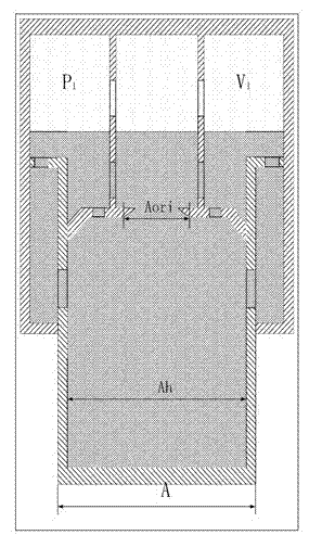

Image

  • Undercarriage buffer
  • Undercarriage buffer
  • Undercarriage buffer

Examples


Embodiment Construction

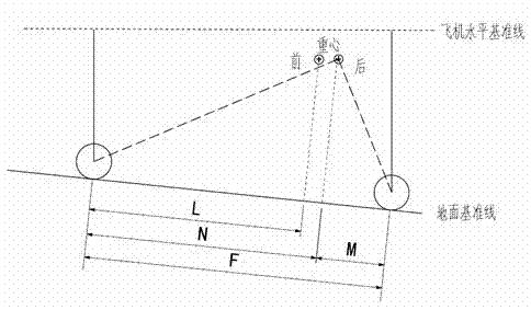
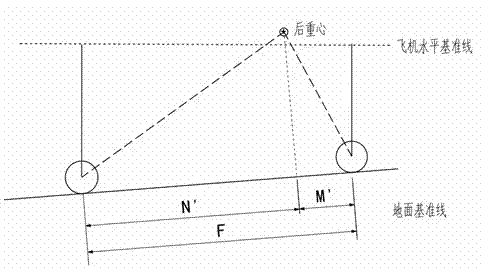
[0107] 1), according to the landing gear size parameters given by the general designer of the landing gear and the center of gravity parameters given by the general designer of the aircraft, determine the schematic diagram of the nose landing gear and the main landing gear of the aircraft in the fully extended state, as shown in figure 1 shown

[0108] 2), such as figure 1 As shown, calculate the maximum parking load F of each pillar of the main landing gear stand_main_max , the maximum parking load F of the nose landing gear stand_nose_max and the minimum parking load of the nose landing gear F stand_nose_min

[0109] f stand_main_max =W(F-M) / (2F)

[0110] (1)

[0111] f stand_nose_max =W(F-L) / F

[0112] (2)

[0113] f stand_nose_min=W(F-N) / F

[0114] (3)

[0115] Among them, W represents the maximum gross weight of the aircraft, which is given by the general designer of the aircraft; F represents the front main wheelbase, which remains unchanged from full extensi...


PUM


Abstract

The invention discloses an undercarriage buffer. At first, load of an undercarriage is calculated when the undercarriage extends to the greatest degree, initial parameters of the undercarriage are calculated according to a traditional method, and wheel axial center and barycentric coordinates under a shutdown compression condition are calculated according to wheel axle center and barycentric coordinates under the condition that the undercarriage extends to the greatest degree; shutdown load of the undercarriage is calculated again; a dynamic compression curve is fit, a largest dynamic compression curved is fit according to largest stroke, and relevant parameters are calculated reversely via the largest dynamic compression curve, so that a complete method is formed. An enforceable calculation scheme of the undercarriage buffer is provided, and the difference between a theoretical value and a test value of load of the undercarriage can be reduced effectively. The largest stroke and the large dynamic compression load simultaneously meet designed requirements of the specific structure and the largest load coefficient under the condition that weight is not increased. Designed results can meet production reality better, and the design period of the undercarriage is shortened to a certain degree.

Description

technical field [0001] The invention relates to the design field of aircraft landing gear buffers. technical background [0002] Landing gear is a special device for aircraft to take off, land, roll and park. Its main function is to bear the static load and dynamic load generated when the aircraft is in contact with the ground, and to prevent damage to the aircraft structure. The landing gear relies primarily on buffers to reduce shock loads during landing shocks and movement on uneven runways. [0003] The design of landing gear cushioning performance is one of the core issues of landing gear design. The quality of landing gear cushioning performance mainly depends on whether the design of the buffer is reasonable, and the appropriateness of the design parameters of the buffer has a decisive impact on the cushioning performance. [0004] In the preliminary design stage of landing gear, technicians generally use the internal design manual of the landing gear industry to des...

Claims


Application Information

Patent Timeline
Patent Type & Authority Applications(China)
IPC IPC(8): F16F9/06F16F9/32B64C25/58
Inventor 聂宏刘向尧魏小辉
Owner NANJING UNIV OF AERONAUTICS & ASTRONAUTICS
Learn More