
Temperature sensor circuit

A temperature sensor and circuit technology, applied in thermometers, instruments, scientific instruments, etc., can solve the problems of high-precision ADC area and power consumption, low voltage, high ADC accuracy requirements, etc., to achieve the effect of easy control and realization

Active Publication Date: 2012-06-06
SHANGHAI FUDAN MICROELECTRONICS GROUP
View PDF5 Cites 25 Cited by
  • Summary
  • Abstract
  • Description
  • Claims
  • Application Information

AI Technical Summary

Problems solved by technology

Its main disadvantages are: 1. ΔV BE The voltage is relatively small, so the accuracy of the ADC is very high, or a special amplifier circuit is required to amplify it
2. The area and power consumption of high-precision ADC are relatively large, which brings difficulties to reduce power consumption and cost in the system
However, the working conditions of this temperature sensor are relatively harsh, and the power supply voltage is required to be much higher than the threshold voltage V of the MOS field effect transistor. TH ;Pulse-Shinking Delay (Pulse-Shinking Delay) which has nothing to do with temperature, please provide Chinese, thank you! The MOS field effect transistor in the unit needs to work under the condition of strong inversion, which is not suitable for the working condition of low voltage and low power consumption; the output code is directly related to the threshold voltage of the MOS field effect transistor and the mobility of the carrier, so that the output The temperature coefficient of the result is greatly affected by the manufacturing process of the integrated circuit, and two-point adjustment of high and low temperature is required

Method used


Image

  • Temperature sensor circuit
  • Temperature sensor circuit
  • Temperature sensor circuit

Examples


Embodiment Construction

[0041] According to Figure 1 ~ Figure 12 , Specifically describe the preferred embodiment of the present invention:

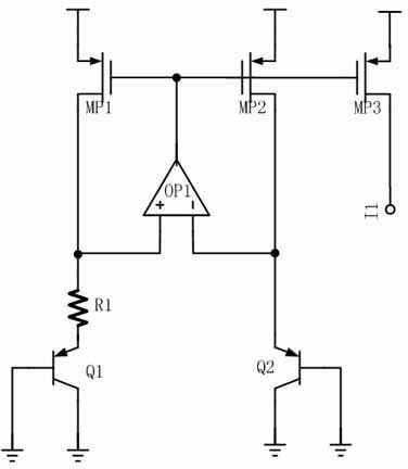
[0042] Such as figure 1 Shown is a schematic structural diagram of a temperature sensor circuit provided by the present invention. The temperature sensor circuit includes a first signal generator 101, a second signal generator 102, and a signal processor 103. The output terminals of the first signal generator 101 and the second signal generator 102 are connected to the input terminal of the signal processor 103.

[0043] The first signal generator 101 generates a temperature-related signal S 1 , The second signal generator 102 generates a signal S that is related to temperature and has a definite functional relationship with the signal generated by the first signal generator 101 2 ; The signal generated by the first signal generator 101 and the signal generated by the second signal generator 102 are input to the signal processor 103 for processing, and the signal p...


PUM


Abstract

The invention relates to a temperature sensor circuit, which comprises a first signal generator, a second signal generator and a signal processor which are connected by a circuit, wherein the output ends of the first signal generator and the second signal generator are connected with the input end of the signal processor. According to the invention, in order to avoid the defect that the traditional time domain signal-based temperature sensor is easily influenced by the manufacture process of an integrated circuit, two time domain signals relative to the temperature are converted into digital codes through the signal processor, the converted signal codes are only relative to the relative values of the parameters of devices in the integrated circuit, and are not relative to absolute values of the parameters of devices in the integrated circuit, thus, the temperature sensor circuit is not easily influenced by the manufacture process of the integrated circuit, and is more easily controlled and realized.

Description

Technical field [0001] The invention relates to a temperature sensor circuit. Background technique [0002] In industrial control and power systems, ambient temperature is an important parameter that needs to be measured. Therefore, temperature sensors are widely used in the system. The integrated circuit temperature sensor has the advantages of small size, low cost, and easy integration. [0003] However, the traditional integrated circuit temperature sensors are based on the base-emitter voltage V of the transistor. BE The temperature characteristic produces a PTAT (Proportional To Absolute Temperature) voltage signal ΔV proportional to the temperature BE Voltage, and then through the high-precision analog-to-digital converter ADC (Analog-to-Digital Converter) BE The voltage is converted to a digital code. The main disadvantages are: 1. ΔV BE The voltage is relatively small, so the accuracy of the ADC is very high, or a special amplifying circuit is needed to amplify it. 2. Th...

Claims


Application Information

Patent Timeline
Patent Type & Authority Applications(China)
IPC IPC(8): G01K7/00
Inventor 郝树森刘阳姚振
Owner SHANGHAI FUDAN MICROELECTRONICS GROUP
Learn More