
Energy-saving high efficiency rapid condenser

A condenser, fast technology, applied in steam/steam condensers, tubular elements, heat exchange equipment, etc., can solve the problems of small heat exchange area and low heat exchange efficiency of heat exchange tubes

Inactive Publication Date: 2012-06-06
王成东
View PDF0 Cites 5 Cited by
  • Summary
  • Abstract
  • Description
  • Claims
  • Application Information

AI Technical Summary

Problems solved by technology

The disadvantage is that the heat transfer efficiency is low due to the small heat transfer area of ​​the existing heat transfer tubes.

Method used


Image

  • Energy-saving high efficiency rapid condenser
  • Energy-saving high efficiency rapid condenser

Examples


Embodiment Construction

[0008] The embodiments of the present invention will be further described in detail below in conjunction with the accompanying drawings.

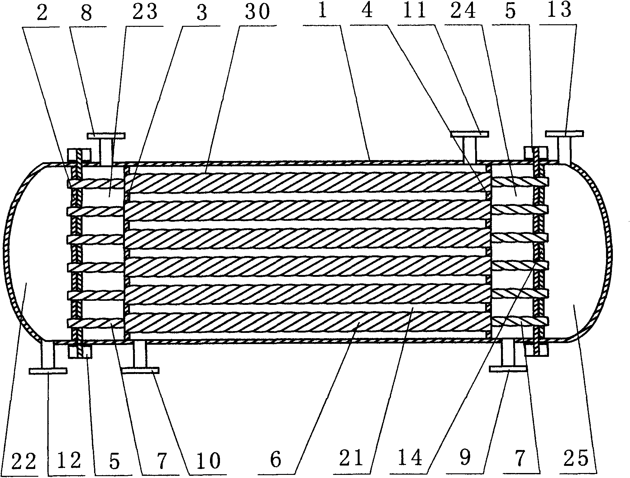
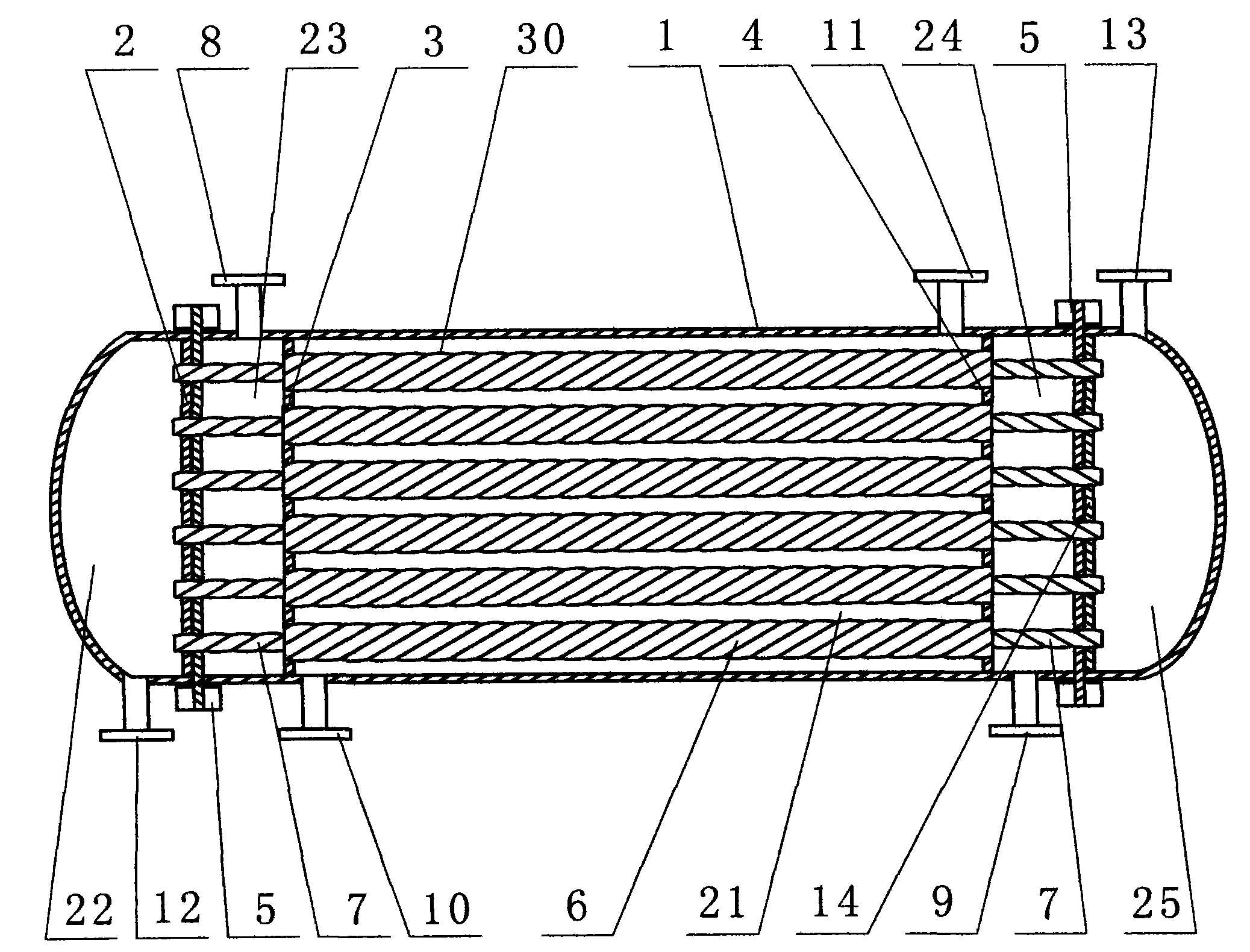
[0009] Such as figure 1 As shown, the energy-saving and high-efficiency fast condenser is composed of a shell 1 and a combined heat exchange tube 30 . The left side inside the housing 1 is provided with a first partition wall 2 and the second partition wall 3, and the right side inside the housing 1 is provided with a third partition wall 4 and a fourth partition wall 14; the first partition wall 2, the second partition wall 3, the third partition wall 4 and the fourth partition 14 are respectively provided with a plurality of through holes (not shown in the figure) for connecting the combined heat exchange tubes 30 . A gas inlet 8 is provided on the housing 1 between the first partition wall 2 and the second partition wall 3; an inner pipe cooling water inlet 12 is provided on the casing 1 outside the first partition wall 2; the shell on ...


PUM


Abstract

The invention discloses an energy-saving high efficiency rapid condenser. The rapid condenser is characterized in that a shell of the condenser is internally provided with a combined type heat exchange tube (30), the combined type heat exchange tube (30) is composed of an outer pipe (6) with larger diameter and an inner pipe with small diameter (7), and the outer pipe (6) is slightly shorter than the inner pipe (7); the pipe wall of the outer pipe (6) is twisted into a spiral shape, and the pipe wall of the inner pipe (7) is twisted into the spiral shape which is opposite to the outer pipe (6); the outer pipe (6) is sleeved on the exterior of the inner pipe (7), and the two ends of the outer pipe (6) are respectively stretched from the inner pipe (7); the two ends of the outer pipe (6) are respectively stretched into thru holes of a second septum (3) and a third septum (4) in the shell (1), and the outer pipe (6), the second septum (3) and the third septum (4) are in hermetic seal connection; and the two ends of the inner pipe (7) are respectively stretched into thru holes of a first septum (2) and a fourth septum (14), and the inner pipe (6), the first septum (2) and the fourth septum (14) are connected in a sealing mode.

Description

[0001] Affiliated technology area [0002] The invention relates to a condensing device for heat exchangers used in industries such as pharmacy, chemical industry, light industry and national defense, in particular to an energy-saving and high-efficiency fast condenser. Background technique [0003] The existing condenser is mainly composed of a shell, a heat exchange tube, and a circulating water pump. During operation, the circulating water pump sprays cooling water on the outside of the heat exchange tube, and after heat transfer, the steam in the heat exchange tube is condensed, and the condensate flows from the The condensate is discharged from the outlet to complete the heat exchange. The disadvantage is that the heat exchange efficiency is low due to the small heat exchange area of ​​the existing heat exchange tube. Contents of the invention [0004] The present invention provides an energy-saving and high-efficiency fast condenser in view of the above-mentioned shor...

Claims


Application Information

Patent Timeline
IPC IPC(8): F28B1/02F28F1/10
Inventor 王成东
Owner 王成东
Learn More