Manufacturing method of a valve

A technology for manufacturing valves and shells, which is applied to valve details, valve devices, valve shell structures, etc., and can solve problems such as deformation

Active Publication Date: 2012-05-30
DANFOSS AS
View PDF6 Cites 3 Cited by
  • Summary
  • Abstract
  • Description
  • Claims
  • Application Information

AI Technical Summary

Problems solved by technology

[0007] The problem with using the MIM process is that relatively thin walls will often deform during welding

Method used


Image

  • Manufacturing method of a valve
  • Manufacturing method of a valve
  • Manufacturing method of a valve

Examples


Embodiment Construction

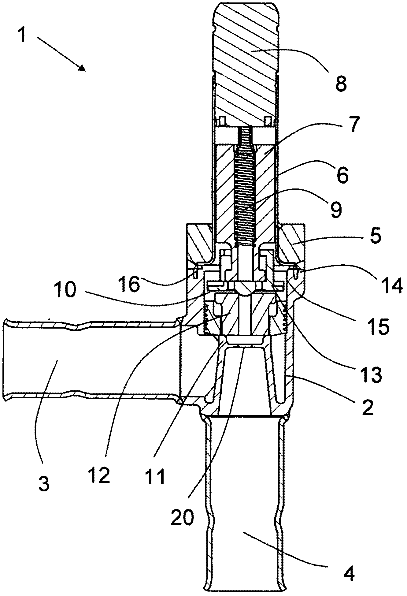
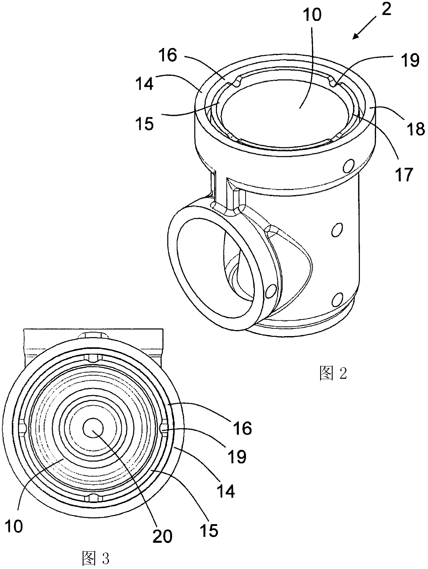
[0021] figure 1 Preferred embodiments of the present invention are shown. The valve 1 comprises a housing 2 , an inlet 3 , an outlet 4 and an upper part 5 . Fastened to the upper part 5 is a guide tube 6 around which the valve comprises a solenoid, but it is not shown in the figure. Inside the guide tube 6 is an armature 7 and an armature top 8 . The spring 9 keeps the valve closed when the armature 7 is not activated by the solenoid. The housing 2 comprises an inner chamber 10 and a valve seat 11 and a nozzle 20 , inside the inner chamber 10 are internal components including a servo piston 12 and a servo closing member 13 . The housing also includes a welding cover 14 , an inner liner 15 and a groove 16 , and the groove 16 is arranged between the welding cover 14 and the inner liner 15 .

[0022] The servo closing member 13 moves up and down inside the inner chamber 10 . The servo-close member 13 moves along the liner 15, so it is very important that the liner 15 is rest...


PUM


Abstract

A method to manufacture a valve using metal injection moulding is disclosed. The valve housing (2) comprises a welding cap (14) for welding the upper part (5) of the valve to the valve housing (2). The welding cap (14) is placed so the upper part (5) can be welded to the housing (2) without damaging the inner cavity (10) of the housing. There is a gap between the welding cap (14) and the inner liner (15) so the heat from the welding do not damage the inner liner (15) allowing the inner parts of the valve to move freely.

Description

technical field [0001] The present invention relates to a method of manufacturing a valve using metal injection molding and welding the valve housing to the upper portion of the valve without damaging the inner cavity of the valve housing. Background technique [0002] Valve housings are usually manufactured by forging or turning or a combination thereof. In a conventional forging process, it is difficult to make details inside the valve and often additional work must be done to further modify the housing after forging, thus wasting valuable material. When manufacturing the valve, the housing is typically assembled to the rest of the valve using a brazed or threaded joint. [0003] Metal Injection Molding (MIM) is a manufacturing method that allows components to be manufactured efficiently and precisely at relatively low cost. In the MIM process, metal powder is mixed with a polymer binder. The MIM material is heated and injected into the mold. The dimensions of the part...

Claims


Application Information

Patent Timeline
Patent Type & Authority Applications(China)
IPC IPC(8): F16K27/10
CPCF16K27/102Y10T29/49426
Inventor 耶斯佩森·贺加兰德·霍耶汉斯·库尔特·彼德森埃里克·托马斯·博恩德奥尔·莫藤森
Owner DANFOSS AS
Why Eureka
Try Eureka