Sulfur recovery plant tail gas treatment process

A tail gas and gas flow technology, applied in the direction of gas treatment, separation methods, chemical instruments and methods, etc., to achieve the effect of reducing investment costs and minimizing capital requirements

Active Publication Date: 2012-05-30
EXXON RES & ENG CO
View PDF16 Cites 12 Cited by
  • Summary
  • Abstract
  • Description
  • Claims
  • Application Information

AI Technical Summary

Problems solved by technology

Based on these expectations, the Sulfreen process (similar to Super Claus technology) may become a regrettable investment when implementing lower sulfur emissions / higher total sulfur recovery required by future regulations

Method used


Image

  • Sulfur recovery plant tail gas treatment process
  • Sulfur recovery plant tail gas treatment process
  • Sulfur recovery plant tail gas treatment process

Examples


Embodiment Construction

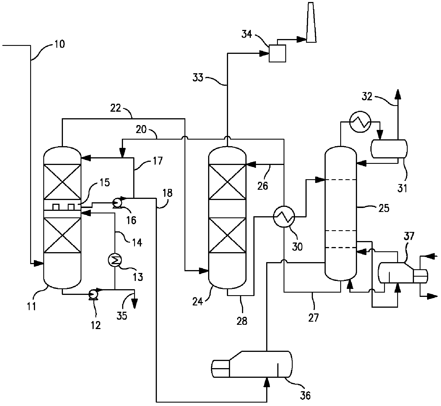
[0022] Exhaust gas treatment device

[0023] This figure illustrates an exemplary configuration for the exhaust gas treatment method of the present invention. The off-gas from the two- or three-stage Claus unit enters the unit via line 10 . At this point, in a conventional BSR or SCOT unit, the tail gas will be sent to a reducing gas generator (RGG), where hydrogen is produced by substoichiometric combustion of natural gas for almost all non-H 2Catalytic reduction of S sulfur components. Passing the Claus tail gas through the RGG typically heats the gas to a temperature of 290-340°C. Alternatively, an exhaust gas preheater can be used to heat the exhaust gas and add H 2 The stream is used for the hydrogenation reaction. SO in the hydrogenation reactor 2 and elemental sulfur are converted by hydrogenation, while CO, COS and CS 2 is hydrolyzed to CO 2 , convert any CO produced into CO by the water-gas shift reaction 2 . This heated gas mixture then enters a conventional...


PUM


Abstract

A process for the removal of hydrogen sulfide from a gas stream in which the gas stream is first passed through a Claus unit operating at a sub-stoichiometric ratio (H2S: SO2) of greater than 2:1 to produce a tail gas stream comprising less than 2000 vppm SO2. This tail gas stream is then treated to increase the sulfur recovery to at least 99.5% by first directly cooling the tail gas stream by contact with water as a coolant, followed by contacting the gas stream with a circulating stream of a dilute, absorbent solution of a severely sterically hindered secondary aminoether alcohol to further cool the gas stream, and then removing the H2S from the stream using a stronger absorbent solution of a severely sterically hindered secondary aminoether alcohol.

Description

technical field [0001] The present invention relates to a process for extracting sulfur from a gas stream containing sulfur compounds, and more particularly to a process for desulphurizing tail gas from a Claus unit. Background technique [0002] Typically, sour gas streams in oil refineries and gas plants are desulphurized by the Claus process. The Claus process is carried out in two main process steps. In the first, by combusting about one-third of the H in the gas stream 2 S produces sulfur dioxide, which is then combined with the remaining H 2 The S reaction produces elemental sulfur, thereby converting hydrogen sulfide to elemental sulfur at a temperature of about 1000 °C. The molten sulfur formed at this stage is then condensed and removed, the H 2 S and SO 2 The reaction between them continues in a second catalytic step in which elemental sulfur is produced over an alumina catalyst at temperatures between 200-350°C. The Claus reaction can be expressed by the fol...

Claims


Application Information

Patent Timeline
Patent Type & Authority Applications(China)
IPC IPC(8): B01D53/14
CPCB01D2252/2025B01D53/1406B01D53/523C01B17/0456B01D53/1468B01D2252/502B01D2257/304B01D2258/00B01D2252/20405B01D2252/103B01D2257/302C01B17/60C01B17/167B01D2252/20484B01D53/1493B01D53/1481B01D2252/20426B01D53/14B01D53/48B01D53/52B01D53/78
Inventor J·N·伊恩加尔D·佩里R·B·费迪施
Owner EXXON RES & ENG CO
Why Eureka
Try Eureka