Method for preparing composite material
A technology of composite materials and dielectric materials, applied in the direction of electrical components, antennas, etc., can solve the problems of not being able to achieve isotropy, and achieve the effect of achieving isotropy and simple preparation
- Summary
- Abstract
- Description
- Claims
- Application Information
AI Technical Summary
Problems solved by technology
Method used
Image
Examples
Embodiment 1
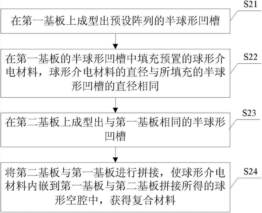
[0022] see figure 2 , is a flow chart of a preparation method of a composite material provided in Embodiment 1 of the present invention, the preparation method comprising:
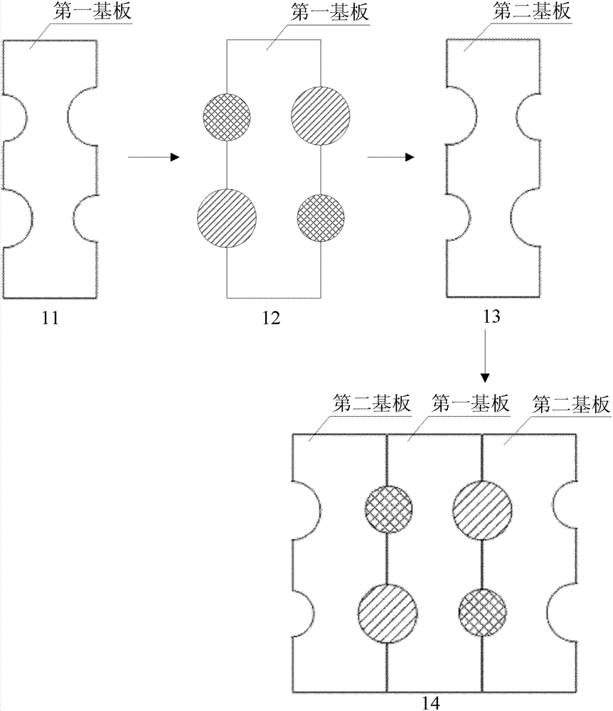
[0023] S21: Forming a preset array of hemispherical grooves on the first substrate.
[0024] Specifically, CNC machine tools or electric discharge machine tools can be used for processing.
[0025] S22: filling the hemispherical groove of the first substrate with a preset spherical dielectric material, the diameter of the spherical dielectric material being the same as the diameter of the filled hemispherical groove.
[0026] Wherein, the dielectric constant of the spherical dielectric material is greater than that of the first substrate material; the diameter of each spherical dielectric material is on the order of millimeters.
[0027] S23: Forming the same hemispherical groove on the second substrate as the first substrate.
[0028] Wherein, the materials of the second substrate and the first substr...
Embodiment 2
[0033] see image 3 , is a flow chart of a preparation method of a composite material provided in Embodiment 2 of the present invention, the preparation method comprising:
[0034] S31: Forming a preset array of hemispherical grooves on the first substrate. Specifically, CNC machine tools or electric discharge machine tools can be used for processing.
[0035] Wherein, the first substrate is a dielectric material substrate. For example, the material of the first substrate is Teflon.
[0036] S32: filling all the hemispherical grooves of the first substrate with a preset spherical dielectric material, the diameter of the spherical dielectric material being the same as the diameter of the filled hemispherical grooves.
[0037] Wherein, the diameter of each spherical dielectric material is on the order of millimeters; the dielectric constant of each spherical dielectric material is greater than the dielectric constant of the first substrate; the material types of each spherica...
Embodiment 3
[0047] see Figure 4 , is a flow chart of a preparation method of a composite material provided in Embodiment 3 of the present invention, and the preparation method includes:
[0048] S41: Forming a preset array of hemispherical grooves on the first substrate. Specifically, CNC machine tools or electric discharge machine tools can be used for processing.
[0049] Wherein, the first substrate is a dielectric material substrate. For example, the material of the first substrate is Teflon.
[0050] S42: filling the partial hemispherical groove of the first substrate with a preset spherical dielectric material, the diameter of the spherical dielectric material being the same as the diameter of the filled hemispherical groove, and filling air in the remaining part of the hemispherical groove.
[0051] Wherein, the dielectric constant of each spherical dielectric material is greater than the dielectric constant of the first substrate; the material types of each spherical dielectri...
PUM
 Abstract
Description
Claims
Application Information
 - R&D
- Intellectual Property
- Life Sciences
- Materials
- Tech Scout
- Unparalleled Data Quality
- Higher Quality Content
- 60% Fewer Hallucinations
Browse by: Latest US Patents, China's latest patents, Technical Efficacy Thesaurus, Application Domain, Technology Topic, Popular Technical Reports.
© 2025 PatSnap. All rights reserved.Legal|Privacy policy|Modern Slavery Act Transparency Statement|Sitemap|About US| Contact US: help@patsnap.com


