Novel five-axis linkage parallel-serial numerical control machine tool
A five-axis linkage, CNC machine tool technology, used in metal processing machinery parts, large fixed members, metal processing equipment and other directions, can solve the problems of motion parameter coupling, poor structural symmetry, few mechanism prototypes, etc., to achieve good rigidity and easy control. , the effect of promoting the application
- Summary
- Abstract
- Description
- Claims
- Application Information
AI Technical Summary
Problems solved by technology
Method used
Image
Examples
specific Embodiment approach 1
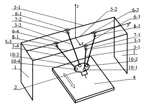
[0013] Specific embodiment one: the five-axis linkage and series CNC machine tool of the present embodiment adopts a vertical structure, which includes a frame 1, a motion platform 2 and connecting rods, and there are four connecting rods, and one end of the four connecting rods is connected to the frame 1 connection, the other ends of the four connecting rods are all hinged with the motion platform 2; the motion platform 2 is arranged under the frame 1, and during work, a tool for processing is installed on the motion platform 2; on the motion platform 2 There is also a mobile workbench 4 below, and the workpiece to be processed is fixed on the mobile workbench 4.
[0014] The four connecting rods are connected to the moving platform 2 through ball joints, which can realize the movement of the connecting rods in all directions relative to the moving platform, and the four ball joints are separated by 90 degrees on the plane of the moving platform 2 The symmetrical arrangement...
specific Embodiment approach 2
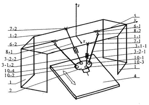
[0017] Specific embodiment two: the difference between this embodiment and specific embodiment one is that a slideway 5 is fixed on the frame 1, and the slideway 5 is one, and two slide blocks are arranged on the slideway 5; Two of the connecting rods are fixed-length connecting rods, and the two fixed-length connecting rods are respectively connected to the two sliders through rotating pairs; the other two connecting rods among the four connecting rods are telescopic connecting rods, and the telescopic connecting rods The rod and the frame 1 are connected by a Hooke hinge.
[0018] The overall structure of this embodiment is as follows figure 2 As shown in the figure, the coordinate system is established, the Y axis is along the direction of the slideway 5, the X axis is in the plane formed by the slideway 5 and the fixed rods 1.1, 1.2 of the frame 1, and the Z axis is vertically upward. The motion platform 2 is connected to the frame 1 and the fixed rod 1 of the fr...
specific Embodiment approach 3
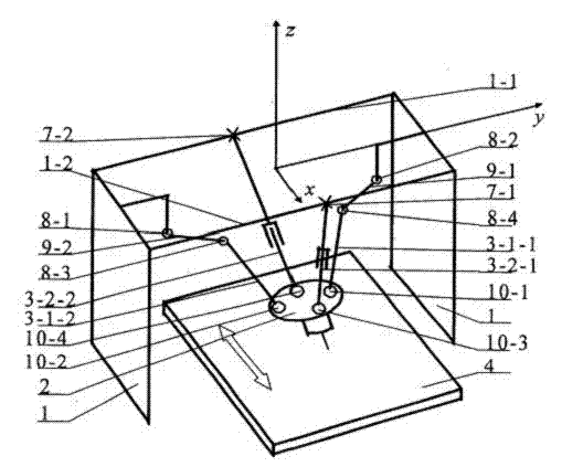
[0019] Embodiment 3: The difference between this embodiment and Embodiment 1 is that two cranks are installed on the frame 1, and the two cranks are respectively connected with the frame 1 through a rotating pair; two of the four connecting rods are The first connecting rod is a fixed-length connecting rod, and the two fixed-length connecting rods are respectively connected to the two cranks through the rotating pair; the other two connecting rods in the four connecting rods are telescopic connecting rods, and the two telescopic connecting rods are respectively connected to the frame 1 connected by a Hooke hinge.
[0020] The overall structure of this embodiment is as follows image 3 As shown, the coordinate system is established as shown in the figure, and the X-axis is on the fixed rod 1.1, 1.1 of the rack 1. In the plane formed by Zhi, the Z axis is vertical upward, the Y axis is parallel to the fixed rods 1-1, 1.2 of the frame 1, and the motion platform 2 passes ...
PUM
 Abstract
Description
Claims
Application Information
 - Generate Ideas
- Intellectual Property
- Life Sciences
- Materials
- Tech Scout
- Unparalleled Data Quality
- Higher Quality Content
- 60% Fewer Hallucinations
Browse by: Latest US Patents, China's latest patents, Technical Efficacy Thesaurus, Application Domain, Technology Topic, Popular Technical Reports.
© 2025 PatSnap. All rights reserved.Legal|Privacy policy|Modern Slavery Act Transparency Statement|Sitemap|About US| Contact US: help@patsnap.com


