Eureka AIR delivers breakthrough ideas for toughest innovation challenges, trusted by R&D personnel around the world.

Roof runoff and diversion catchment

A water collector and runoff technology, which is applied in the field of environmental pollution prevention and control, can solve the problems of increasing the cost of treatment, increasing the difficulty of runoff treatment and utilization, and inconvenience in construction, so as to achieve the effects of avoiding pollution, increasing aesthetics, and reducing construction volume

Inactive Publication Date: 2012-05-23
HUAZHONG AGRI UNIV
View PDF6 Cites 1 Cited by
  • Summary
  • Abstract
  • Description
  • Claims
  • Application Information

AI Technical Summary

Problems solved by technology

Among them, some equipment collects all the runoff, which leads to the mixing of the initial highly polluted runoff and the later clean runoff, which increases the difficulty of processing and utilizing the collected runoff; the other part of the equipment separates the initial runoff and the later runoff. Collection, but the diversion equipment and collection equipment are completely separated, so that diversion and collection equipment need to be installed separately during construction, which increases the cost of treatment and brings inconvenience to construction

Method used


Image

  • Roof runoff and diversion catchment
  • Roof runoff and diversion catchment

Examples


Embodiment 1

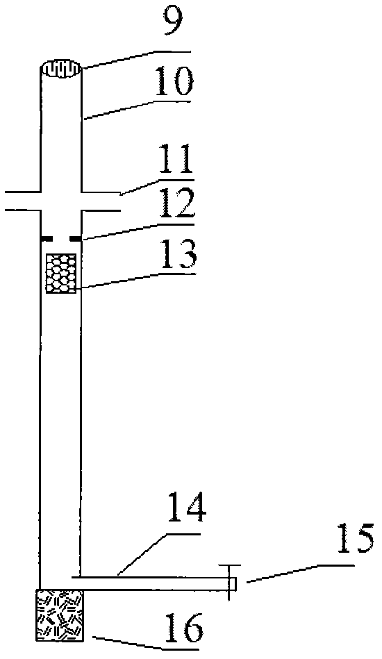
[0027] Such as figure 1 As shown, this embodiment includes: a convex filter screen 1 , a rain downpipe 2 , a hose 3 , a shunt pipe 6 , a water reservoir 5 , an overflow pipe 8 and a first shunt valve 7 . Wherein: the convex filter screen 1 is connected to the rain drop pipe 2, the end of the rain drop pipe 2 is connected to the hose 3, the end of the hose 3 is connected to the shunt pipe 6, and the shunt pipe 6 is located in the center of the water storage 5 and arranged vertically , the overflow pipe 8 is arranged on the outer wall of the upper part of the water storage 5, the first diverter valve 7 is located under one side of the water storage 5, the convex filter screen 1 is located at the water outlet of the eaves gutter, and the water storage 5 Located below the convex filter screen 1, its installation position forms a level difference with the convex filter screen 1. The distribution pipe 5 is composed of a concave filter screen 9 , a vertical pipe 10 , a distribution ...


PUM


Abstract

The invention relates to a non-point source pollution control and roof runoff and diversion collection and utilization device, which comprises a strainer, a pipeline and a water collection device, and is characterized in that: the convex strainer is connected with a rainwater down pipe, and the tail end of the rainwater down pipe is connected with a hose; the tail end of the hose is connected with a diversion pipe, and the diversion pipe is positioned at the center of a water storage device; an overflow pipe is arranged on the outer wall of the upper part of the water storage device, and a first diversion valve is positioned below one side of the water storage device; the convex strainer is positioned at a water outlet of an eave gutter, and the water storage device is positioned below the convex strainer; and the installation position of the water storage device forms a position difference with the convex strainer 1. A concave strainer is arranged at the upper end of a vertical pipe,and a diversion port is positioned on the outer side wall of the upper part of the vertical pipe; a clamping seat is positioned below the diversion port and is arranged on the inner wall of the vertical pipe, a float is arranged in the vertical pipe from the lower part of the clamping seat to a transverse pipe joint and is in a cylindrical shape, and the diameter of the float is slightly smaller than that of the vertical pipe. The bottom end of the vertical pipe is fixedly arranged on a concrete base, and the concrete base is arranged at the bottom of the center of the water storage device; and a transverse pipe clings to the base, and a second diversion valve is arranged at the tail end of the transverse pipe.

Description

technical field [0001] The invention belongs to the technical field of environmental pollution prevention and control, and specifically relates to a treatment device for non-point source pollution control and rainwater reuse. A small water collector is used to divert the initial runoff from the roof, and then collect and utilize the later clean runoff. Background technique [0002] With the acceleration of urbanization in my country, the flow of urban surface runoff is increasing, and the destructive power to the water environment is also increasing. Roof runoff accounts for a large proportion of urban surface runoff, and it is also one of the key areas for urban surface runoff control. Roofs can be divided into asphalt roofs, tile roofs, and cement roofs according to different roof materials. The degree of runoff pollution produced by each of them also varies with different roof materials. However, they all have a common feature, that is, the concentration of pollutants is...

Claims


Application Information

Patent Timeline
IPC IPC(8): E03B3/02E03B3/03
CPCY02A20/00Y02A20/108
Inventor 赵建伟高勇朱端卫周文兵华玉妹范俊楠张钰
Owner HUAZHONG AGRI UNIV
Why Eureka
Eureka Blog
Learn More