Fuel-Oil Heat Exchanger

Active Publication Date: 2020-06-25
SAFRAN AERO BOOSTERS SA
View PDF0 Cites 1 Cited by
  • Summary
  • Abstract
  • Description
  • Claims
  • Application Information

AI Technical Summary

Benefits of technology

The proposed heat exchanger has a special tubular mesh network that allows fluid to flow through all the meshes, ensuring optimal heat exchange. This results in a smaller, lighter exchanger with the same efficiency. The curved pipes and repetitive crossing zones promote turbulence and improve heat transfer. The mesh network also eliminates the need for additional mechanical supports and prevents clogging in extreme cold. The exchanger is a single piece with good resistance to stress and no risk of leakage.

Problems solved by technology

The known exchanger does not allow a homogeneous distribution of the fuel flowing through the channels.
This implies that the heat exchange capacity is not fully exploited in all areas of the cavity.
This state-of-the-art exchanger also does not allow a homogeneous distribution of the two fluids.
Such an exchanger has the disadvantage that the surfaces in contact with the two fluids are identical, which is not always interesting for an exchanger, particularly due to the different flow rates for the two fluids involved.
However, the fins are difficult to integrate into a so-called gyroid structure.

Method used


Image

  • Fuel-Oil Heat Exchanger
  • Fuel-Oil Heat Exchanger
  • Fuel-Oil Heat Exchanger

Examples


Embodiment Construction

[0016]The present application aims to solve at least one of the problems posed by the prior art. The purpose of the present application is to optimize heat exchange, pressure drops and possibly the operation of a turbomachine. The present application also aims to provide a simple and compact solution.

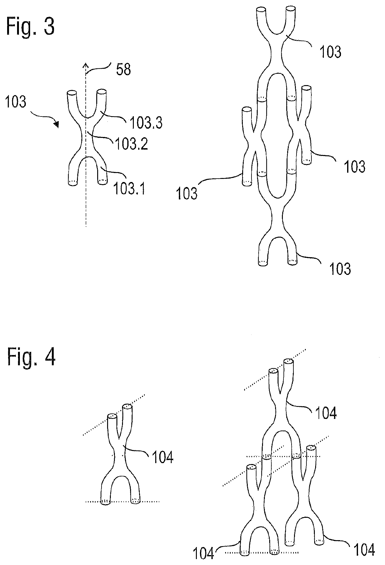
[0017]The present application relates to a heat exchanger between a first fluid and a second fluid, in particular a turbomachine heat exchanger, the heat exchanger comprising: a reference direction; and a network of tubes delimiting an inner passage for the first fluid, the network of meshes comprising a plurality of meshes, each of the meshes being formed, successively in the reference direction, of at least two curvilinear branches, called anterior branches, of a junction where the two anterior branches meet, and of at least two curvilinear branches, called posterior, diverging from the junction; wherein the plurality of meshes comprises at least a first mesh, a second mesh and a thir...


PUM


Abstract

A turbine engine heat exchanger for exchanging heat between a first fluid and a second fluid includes a reference axis, a network of tubular meshes having a plurality of meshes each of which is formed, successively in a reference direction, of at least two curvilinear branches, called anterior branches, of a junction where the two anterior branches meet, and of at least two curvilinear branches, called posterior branches, diverging from the junction, wherein the meshes are stacked in staggered rows.

Description

[0001]This application claims priority under 35 U.S.C. § 119 to Belgium Patent Application No. 2018 / 5931, filed 21 Dec. 2018, titled “Fuel-Oil Heat Exchanger,” which is incorporated herein by reference for all purposes.BACKGROUND1. Field of the Application[0002]The present application relates to the field of turbomachine heat exchangers. More precisely, the present application proposes an oil / fuel heat exchanger or a turbomachine. The present application also relates to an axial turbomachine, in particular a turbojet engine. The present application also proposes a process for making a heat exchanger.2. Description of Related Art[0003]Document US 2018 / 0057942 A1 discloses an oil / fuel exchanger for an aircraft and made by additive manufacturing. This exchanger comprises a group of straight parallel channels formed between two manifolds. The fuel flows through these channels and is heated by oil that flows through a cavity delimited by guide walls and a cylindrical wall. The known exch...

Claims


Application Information

Patent Timeline
IPC IPC(8): F28D7/10
CPCF28D7/10F28D7/0075F28F1/00F28F9/001F28F27/00F02C7/141F28F2210/02F28D7/005F28D7/08F28D7/0041F28D7/0058F28F2250/06F28D2021/0026F02C7/224F02C7/14F05D2260/213F05D2230/31F05D2260/98Y02T50/60
Inventor KOEUNE, ROXANEFELLIN, NICOLAS
Owner SAFRAN AERO BOOSTERS SA
Why Eureka
Try Eureka