Voltage/current double-loop control device and chip
A technology of voltage, current and control devices, which is applied in the direction of control/regulation systems, regulation of electrical variables, instruments, etc., and can solve problems such as distortion and affecting the accuracy of double-loop control systems
- Summary
- Abstract
- Description
- Claims
- Application Information
AI Technical Summary
Problems solved by technology
Method used
Image
Examples
Embodiment 1
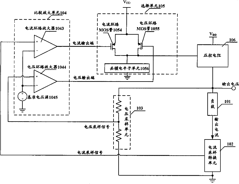
[0070] In this embodiment, the current loop MOS transistor 3054 and the voltage loop MOS transistor 3055 use PMOS transistors, and a current sink is used to realize the function of the common-mode level subunit 1056 .
[0071] Such as image 3 As shown, at this time, the selection unit 305 in the circuit specifically includes: a current loop MOS transistor 3054, a voltage loop MOS transistor 3055, and a current sink 3056, and the voltage output terminal of the comparison amplifier unit 304 is connected to the gate of the voltage loop MOS transistor 3055. pole, the current output terminal of the comparison amplifier unit 304 is connected to the gate of the current loop MOS transistor 3054, the source of the current loop MOS transistor 3054 is connected to the source of the voltage loop MOS transistor 3055, and connected to the circuit voltage source, the current The drain of the loop MOS transistor 3054 is connected to the drain of the voltage loop MOS transistor 3055, and conn...
Embodiment 2
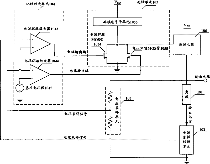
[0078] In this embodiment, the current loop MOS transistor 4054 and the voltage loop MOS transistor 4055 use NMOS transistors, and a current sink is used to realize the function of the common-mode level subunit 1056 .
[0079] Such as Figure 4 As shown, at this time, the selection unit 405 in the circuit specifically includes: a current loop MOS transistor 4054, a voltage loop MOS transistor 4055, and a current sink 4056, and the voltage output terminal of the comparison amplifier unit 404 is connected to the gate of the voltage loop MOS transistor 4055. pole, the current output terminal of the comparison amplifier unit 404 is connected to the gate of the current loop MOS transistor 4054, the source of the current loop MOS transistor 4054 is connected to the source of the voltage loop MOS transistor 4055, and grounded, the current loop MOS The drain of the tube 4054 is connected to the drain of the voltage loop MOS tube 4055, and connected to the negative pole of the current ...
Embodiment 3
[0087] In this embodiment, the current loop MOS transistor 5054 and the voltage loop MOS transistor 5055 use PMOS transistors, and MOS transistors and voltage sources are used to realize the function of the common-mode level subunit 1056 .
[0088] Such as Figure 5 As shown, at this time, the selection unit 505 in the circuit specifically includes: a current loop MOS transistor 5054, a voltage loop MOS transistor 5055, a first amplifying MOS transistor 5056, a second amplifying MOS transistor 5057, a first voltage source 5058 and a second amplifying MOS transistor 5057. Two voltage sources 5059, wherein, the voltage output terminal of the comparison and amplification unit 504 is connected to the gate of the voltage loop MOS transistor 5055, the current output terminal of the comparison and amplification unit 504 is connected to the grid of the current loop MOS transistor 5054, and the current loop MOS transistor The source of the 5054 is connected to the source of the voltage...
PUM
 Abstract
Description
Claims
Application Information
 - R&D
- Intellectual Property
- Life Sciences
- Materials
- Tech Scout
- Unparalleled Data Quality
- Higher Quality Content
- 60% Fewer Hallucinations
Browse by: Latest US Patents, China's latest patents, Technical Efficacy Thesaurus, Application Domain, Technology Topic, Popular Technical Reports.
© 2025 PatSnap. All rights reserved.Legal|Privacy policy|Modern Slavery Act Transparency Statement|Sitemap|About US| Contact US: help@patsnap.com


