Hydraulic differential pilot opening mechanism

An opening mechanism and differential technology, applied in the field of hydraulic components, can solve the problems of easy vibration and howling of the pilot valve core, large impact of the pilot valve, and short life.

Inactive Publication Date: 2012-05-16
GUANGXI LIUGONG MASCH CO LTD
View PDF5 Cites 10 Cited by
  • Summary
  • Abstract
  • Description
  • Claims
  • Application Information

AI Technical Summary

Problems solved by technology

[0003] The purpose of the present invention is to solve the disadvantages that the pilot valve of the existing hydraulic pilot opening mechanism is easily damaged due to large impact and has a short service life, and the pilot valve core is in a floating state when the pilot valve is opened, and it is easy to generate vibration and howling. Hydraulic differential pilot opening mechanism with good stability, low noise and long service life

Method used


Image

  • Hydraulic differential pilot opening mechanism
  • Hydraulic differential pilot opening mechanism
  • Hydraulic differential pilot opening mechanism

Examples


Embodiment 1

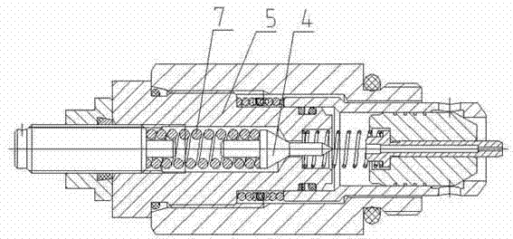
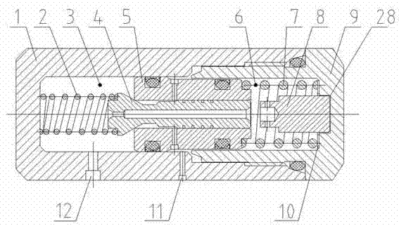
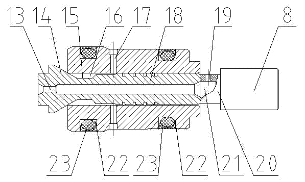
[0025] Such as figure 2As shown, the hydraulic differential pilot opening mechanism includes a valve body 1 and a bonnet 9 screwed to the valve body. A pilot valve cavity is formed in the valve body and the bonnet, and a pilot valve is slidably arranged in the pilot valve cavity. The inner side is the first cavity 3, the valve body 1 is provided with an oil inlet 12 communicating with the first cavity 3, the second cavity 6 is provided on the outside of the pilot valve, and the pilot valve core 4 is provided with a connection with the first cavity 3 and the orifice 13 of the second cavity 6, such as image 3 As shown, the pilot valve includes a pilot valve core 4 and a pilot valve seat 5, and the pilot valve seat 5 is in sliding fit with the inner wall of the pilot valve cavity. It includes a guide portion 18 at the head, a sealing cone 14 at the tail, and a connecting portion 15 connecting the guiding portion and the sealing cone. The sealing cone 14 is located in the first...

Embodiment 2

[0028] Such as Figure 5 As shown, compared with the first embodiment, the difference is that: the outer side of the pilot valve seat 5 has a cylindrical concave cavity, and the side wall of the concave cavity is slidingly fitted with the side wall of the limit post 8, and the pilot valve seat 5 The second cavity 6 is formed with the limiting post 8 , and a second sealing groove 26 is provided on the side of the limiting post 8 cooperating with the pilot valve seat 5 , and a second sealing ring 27 is embedded in the second sealing groove. The bonnet 9 is provided with a fixed cap 24, and the center of the fixed cap is provided with a limit post fixing hole 25. The limit post is inserted in the fixed hole 25, and is fixedly connected with the fixed cap by tight fit or screw threads. The side surface is connected with the inner surface of the bonnet 9, the pressure regulating spring 7 is in contact with the fixed cap, and a pressure regulating gasket 10 is arranged between the t...

Embodiment 3

[0030] Such as Image 6 As shown, compared with the first embodiment, the difference is that a sealing sleeve 29 is provided on the outside of the small diameter section of the pilot valve seat 5, and the inner side wall of the sealing sleeve 29 is in contact with the outer side wall of the small diameter section of the pilot valve seat 5. Slip fit, the two ends of the sealing sleeve 29 are in contact with the valve body 1 and the bonnet 9 respectively, and are axially positioned by the extrusion of the bonnet 9 . In this embodiment, by providing the sealing sleeve 29, the coaxiality requirement between the sealing sleeve 29 and the pilot valve seat 5 can be easily met during the manufacturing process, which can reduce the difficulty of manufacturing.


PUM


Abstract

The invention discloses a hydraulic differential pilot opening mechanism. The mechanism aims to overcome the defect that the service life of a pilot valve plug and a pilot valve bush is easy to reduce, and the pilot valve plug and the pilot valve bush vibrate seriously and are large in noise due to large impact between the pilot valve plug and the pilot valve bush in the conventional hydraulic pilot opening mechanism. In the pilot opening mechanism, a differential pilot valve is arranged in a pilot valve cavity; a first cavity which is communicated with an oil inlet is formed on the inner side of the pilot valve; a second cavity which is communicated with the first cavity through an orifice is formed on the outer side of the pilot valve; a pilot valve plug is arranged in a pilot valve seat in a slidable way; a sealing cone of the pilot valve plug is positioned in the first cavity and is connected with a first buffer spring; the side of the second cavity is provided with a pressure regulation spring which is connected with the pilot valve seat; and a pilot valve gap between the pilot valve seat and the pilot valve plug, a radial through hole and an oil outlet form a leakage oil way for opening the pilot valve. Through the differential pilot valve, the inverse pilot valve plug, the buffer spring, the axial movable pilot valve seat, the pilot valve plug and the damping action of the pilot valve gap, the impact force during closing of the pilot valve is reduced, the pilot valve plug is always in the stable state, and the hydraulic differential pilot opening mechanism has the advantages of small impact, long service life, stability and low noise.

Description

technical field [0001] The invention relates to a hydraulic component of a hydraulic system, in particular to a pilot opening mechanism in the hydraulic system. technical background [0002] In the existing hydraulic control valves such as relief valves and pressure reducing valves, a hydraulic pilot opening mechanism is commonly used to control the hydraulic pressure in the main spool return spring cavity of the control valve, and the hydraulic pressure in the main spool return spring cavity is reduced. Open the main spool. However, in the existing hydraulic pilot opening device, such as figure 1 As shown, the pilot valve sleeve 5 is fixed, and the pilot valve core 4 is positioned in the valve hole of the pilot valve sleeve through the columnar positioning pin on its top and is intermittently matched with the valve hole. This structure uses the pressure regulating spring 7 to To balance the force of the hydraulic oil on the pilot valve core, the stiffness of the pressure ...

Claims


Application Information

Patent Timeline
Patent Type & Authority Applications(China)
IPC IPC(8): F15B13/02
Inventor 高英达唐云娟
Owner GUANGXI LIUGONG MASCH CO LTD
Why Eureka
Try Eureka