Optical film, polarizing plate, image display device, and method for manufacturing optical film
An optical film and transparent substrate technology, applied in the field of optical films, can solve problems such as unfavorable display image visibility or image quality, and achieve the effects of suppressing interference unevenness, suppressing bending, and suppressing film bending
- Summary
- Abstract
- Description
- Claims
- Application Information
AI Technical Summary
Problems solved by technology
Method used
Image
Examples
preparation example Construction
[0268] One example of the production method of the esterified compound is as follows.
[0269] Acetic anhydride (200 mL) was added dropwise to a solution of glucose (29.8 g, 166 mmol) to which pyridine (100 mL) had been added, and the mixture was allowed to react for 24 hours. Thereafter, the resulting solution was concentrated by evaporation and poured into ice water. After allowing the resulting solution to stand for 1 hour, solids were separated from water by filtration with a glass filter. The solid on the glass filter was dissolved in chloroform and subjected to liquid separation with cold water until the system became neutral. The organic phase was separated and dried over anhydrous sodium sulfate. After removing anhydrous sodium sulfate by filtration, chloroform was removed by evaporation, and the residue was further dried under reduced pressure to obtain glucose pentaacetate (58.8 g, 150 mmol, yield: 90.9%). In this regard, the aforementioned monocarboxylic acids ca...
Embodiment 1
[0402] [Preparation of optical film]
[0403] Coating liquids for forming the respective layers were formulated to form the respective layers shown below, whereby Optical Film Samples 1-13 were prepared.
[0404] (preparation of coating solution for hard coat)
[0405] The following composition was put into the mixing tank, stirred, and filtered through a filter made of polypropylene having a pore size of 0.4 μm, thereby preparing a coating solution A-1 for a hard coat layer (solid concentration: 58% by mass).
[0406]
[0407] In a similar manner to the coating liquid A-1 of the hard coat layer, as shown in Table 1 below, the components were mixed and dissolved in a solvent so as to have the ratios shown in Table 1, thereby preparing a hard coat layer Coating solutions A-2 to A-14.
[0408]
[0409]
[0410] Each compound used is shown below.
[0411] Leveling agent (SP-13):
[0412]
[0413] PET30: a mixture of compounds having the following structure produce...
Embodiment 2
[0478] Substrates 1-3 were prepared using dopes B-1 and B-2 shown in Table 3 below in the manner described in paragraphs 41-42 of this specification, respectively.
[0479] table 3
[0480]
[0481] Table 3 (continued)
[0482]
[0483] Optical Films 14 to 18 were prepared in the same manner as Film Sample 1 except for using each of the base materials and coating liquids of the hard coat layer shown in Table 4 below, and in the same manner as those in Table 2, Evaluations were made in terms of interference unevenness and pencil hardness. Here, the base material used in Sample 16 was ZRD60SL (cellulose acylate film having an acetyl substitution degree of 2.86 and a film thickness of 60 μm) produced by Fujifilm Corporation.
[0484] Table 4
[0485]
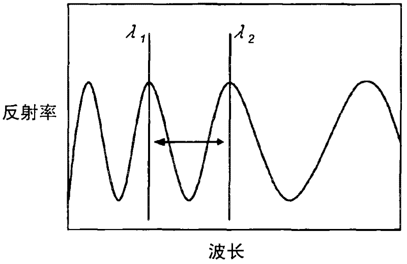
[0486] As shown in Table 4, even in the case of using a thin base material of 40 μm or 60 μm, the optical film of the present invention had high hardness, suppressed interference unevenness, and exhibited excellent perfor...
PUM
| Property | Measurement | Unit |
|---|---|---|
| thickness | aaaaa | aaaaa |
| hydroxyl value | aaaaa | aaaaa |
| particle size | aaaaa | aaaaa |
Abstract
Description
Claims
Application Information
 - R&D
- Intellectual Property
- Life Sciences
- Materials
- Tech Scout
- Unparalleled Data Quality
- Higher Quality Content
- 60% Fewer Hallucinations
Browse by: Latest US Patents, China's latest patents, Technical Efficacy Thesaurus, Application Domain, Technology Topic, Popular Technical Reports.
© 2025 PatSnap. All rights reserved.Legal|Privacy policy|Modern Slavery Act Transparency Statement|Sitemap|About US| Contact US: help@patsnap.com


