
Biogas liquefaction process and device for scattered gas source point

A liquefaction device and biogas technology, applied in liquefaction, refrigeration and liquefaction, compressors, etc., can solve the problems of biogas liquefaction without scattered gas sources, large initial investment in equipment, complex process equipment, etc., to achieve convenient and stable control and adjustment The effect of liquefaction rate and simple process

Inactive Publication Date: 2012-05-09
NANJING FORESTRY UNIV
View PDF8 Cites 13 Cited by
  • Summary
  • Abstract
  • Description
  • Claims
  • Application Information

AI Technical Summary

Problems solved by technology

However, these processes have their own characteristics and cannot be directly applied to biogas liquefaction at scattered gas sources.
The cascade refrigeration cycle liquefaction process has lower energy consumption, but the process equipment is more complicated; the mixed refrigerant refrigeration cycle liquefaction process has a relatively simple process, fewer compressor units, and does not require high refrigerant purity, but the energy consumption is higher than that of the cascade refrigeration cycle. The refrigeration cycle is about 20% higher; the energy consumption of the expansion refrigeration cycle liquefaction process is the lowest, the process is simple, and the processing capacity is large, but the initial investment in equipment is large and a large amount of gas supply is required

Method used


Image

  • Biogas liquefaction process and device for scattered gas source point
  • Biogas liquefaction process and device for scattered gas source point
  • Biogas liquefaction process and device for scattered gas source point

Examples


Embodiment Construction

[0032] In order to further understand the content, characteristics and effects of the present invention, the following examples are given, and detailed descriptions are as follows in conjunction with the accompanying drawings:

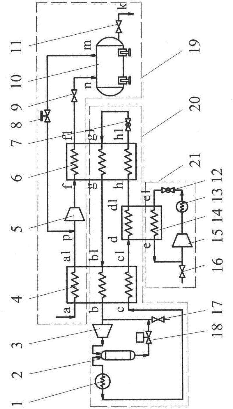
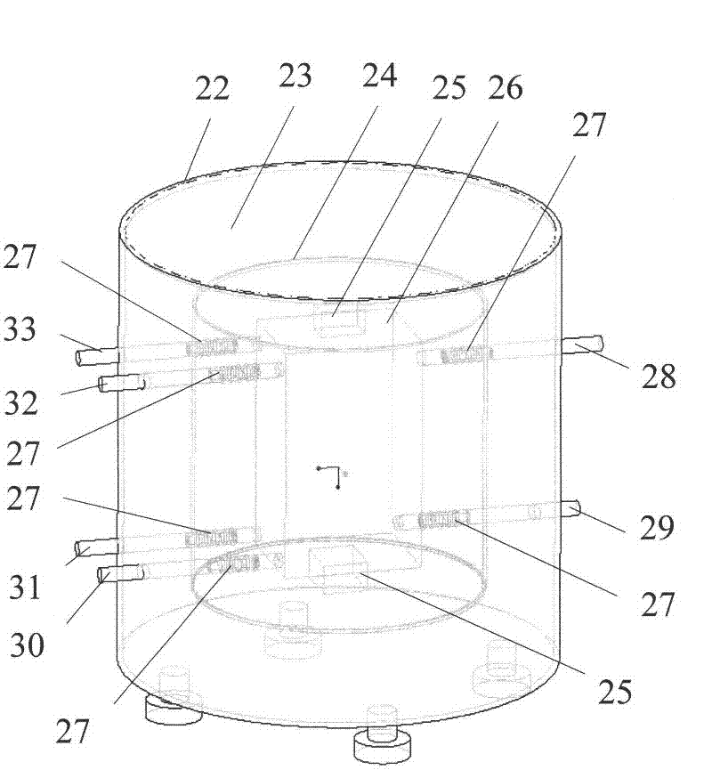
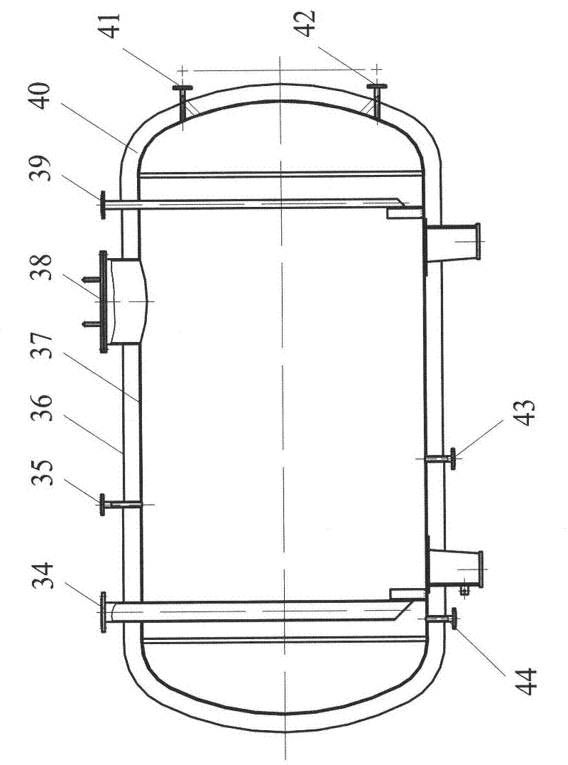
[0033] Such as figure 1 As shown, the biogas liquefaction process and device of the present invention is a cascade refrigeration cycle system composed of a multi-component mixed refrigerant circulation unit 20 and a multi-component mixed refrigerant pre-cooling unit 21, forming a low temperature in the cold box 6, condensing and liquefying raw material biogas. The single refrigerant is propane, and the multi-component mixed refrigerant is a mixture of propane, ethane, methane and nitrogen in a certain mass ratio. The multi-component mixed refrigerant cycle unit 20 is connected in turn by pipelines from the main compressor 3, the oil separator 2, the main condenser 1, the regenerator 4, the pre-cooling heat exchanger 14, the cold box 6, and the main th...


PUM


Abstract

The invention relates to a biogas liquefaction process and a device for a scattered gas source point. The device comprises a multi-component mixed refrigerant pre-cooling unit, a multi-component mixed refrigerant circulating unit and a liquefaction and storage unit, and is characterized in that: the multi-component mixed refrigerant pre-cooling unit and the multi-component mixed refrigerant circulating unit form cascade refrigeration circulation to obtain low temperature to cool and condensate a raw material biogas flowing in the liquefaction and storage unit into a liquid, and the liquefaction and storage unit consists of a regenerator, a raw material biogas compressor, a cold box, a storage inlet cut-off valve and a storage tank; and the multi-component mixed refrigerant circulating unit consists of a main compressor, an oil separator, a main condenser, the regenerator, a pre-cooling heat exchanger, the cold box, a main throttle valve and an oil return solenoid valve, and the multi-component mixed refrigerant pre-cooling unit consists of an auxiliary compressor, an auxiliary condenser, the pre-cooling heat exchanger and an auxiliary throttle valve. The regenerators and the multi-stream plate heat exchangers are used, so that the efficiency of the device is greatly improved; and the throttle valves are used for one-time throttling, so that the flow process is simple, the control and adjustment are convenient, the investment is less, and the device is convenient to move and skid.

Description

technical field [0001] The invention belongs to the key technical field of biomass energy and green manufacturing, and in particular relates to a biogas liquefaction process and device for scattered gas sources. Background technique [0002] The sustainable development of energy is an important pillar of the national economy. The development and utilization of emerging energy and the improvement of the comprehensive utilization efficiency of resources are the direction of my country's future energy development. Analyzing the country's current resource allocation and sustainable development requirements for environmental protection awareness, it is not difficult to see that the development and utilization of clean energy such as natural gas and biogas is and will gradually become an important component of China's energy industry. Biogas - a mixed gas composed of various gases including methane, carbon dioxide, hydrogen sulfide, carbon monoxide, hydrogen, oxygen, nitrogen, etc...

Claims


Application Information

Patent Timeline
IPC IPC(8): F25J1/02F25B9/00
Inventor 孙见君刘英於秋萍涂桥安华洁李佳王培龙马晨波张峻斌
Owner NANJING FORESTRY UNIV
Learn More