Boom element, telescopic boom and construction vehicle

A telescopic boom technology, which is applied in telescopic joints or telescopic boom hinges, engineering vehicles, and telescopic booms, can solve problems such as boom weight, reduce production costs, ensure quality, and lighten the structure. Effect

Active Publication Date: 2012-05-09
LIEBHERR WERK EHINGEN
View PDF5 Cites 2 Cited by
  • Summary
  • Abstract
  • Description
  • Claims
  • Application Information

AI Technical Summary

Problems solved by technology

[0003] Based on the requirement to provide very large boom systems with long booms, the problem arises that a typical telescopic boom is too heavy

Method used


Image

  • Boom element, telescopic boom and construction vehicle
  • Boom element, telescopic boom and construction vehicle
  • Boom element, telescopic boom and construction vehicle

Examples


Embodiment Construction

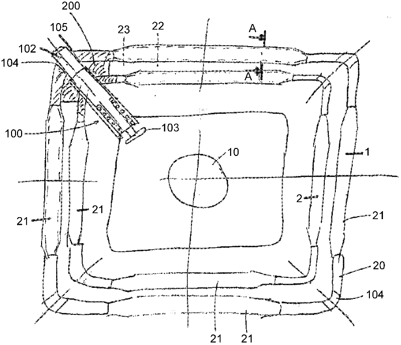
[0053] figure 1 A schematic front view of a part of a telescopic boom according to the invention is shown, wherein here two telescopic joints 1 and 2 are shown. as can be obtained from figure 1 As seen in the figure, a shell-shaped corner rod 20 is used in each telescopic joint 1, 2, 3, 4.

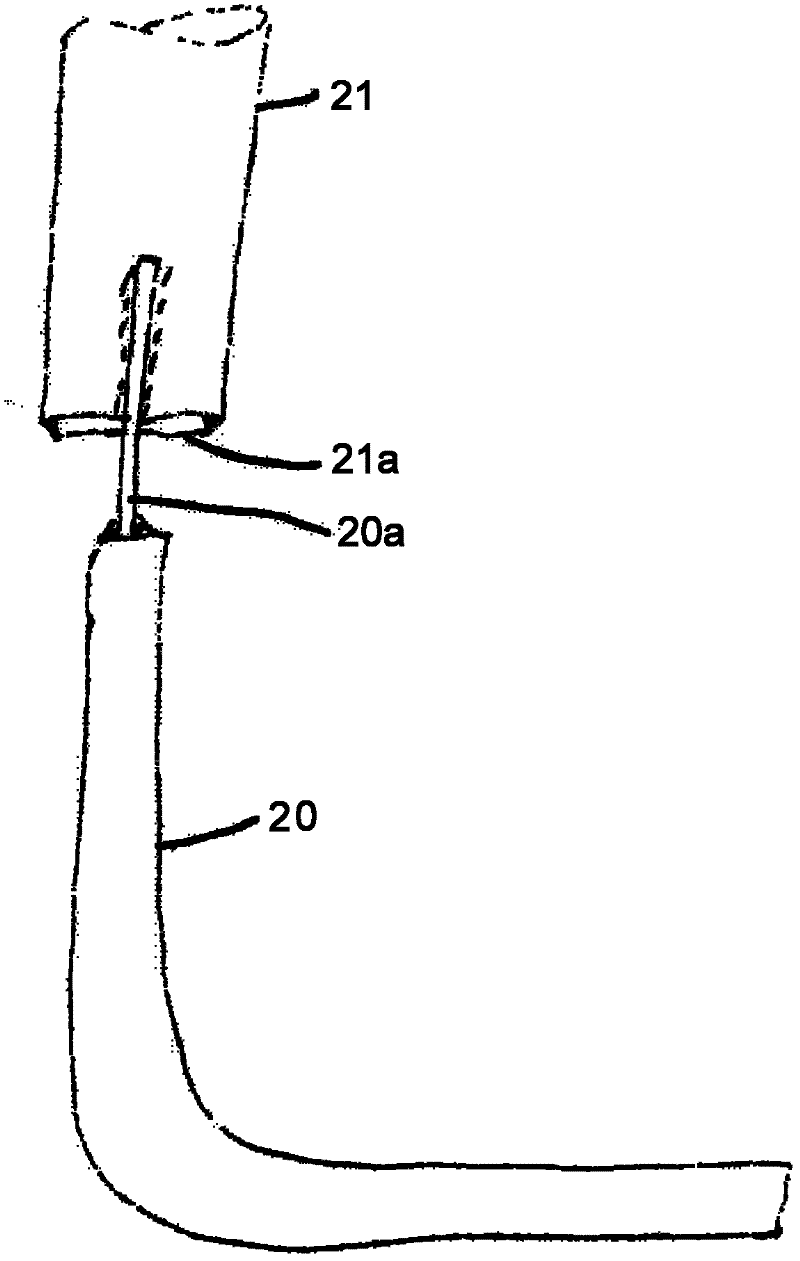
[0054] The corner bar 20 can be produced as folded, bent, from a tubular section or even from an extruded profile. The corner bars 20 are connected by truss bars 21 which are at right angles to the corner bars 20 (called zero bars) or / and also at another angle to the corner bars 20 (called diagonal bars) ground layout.

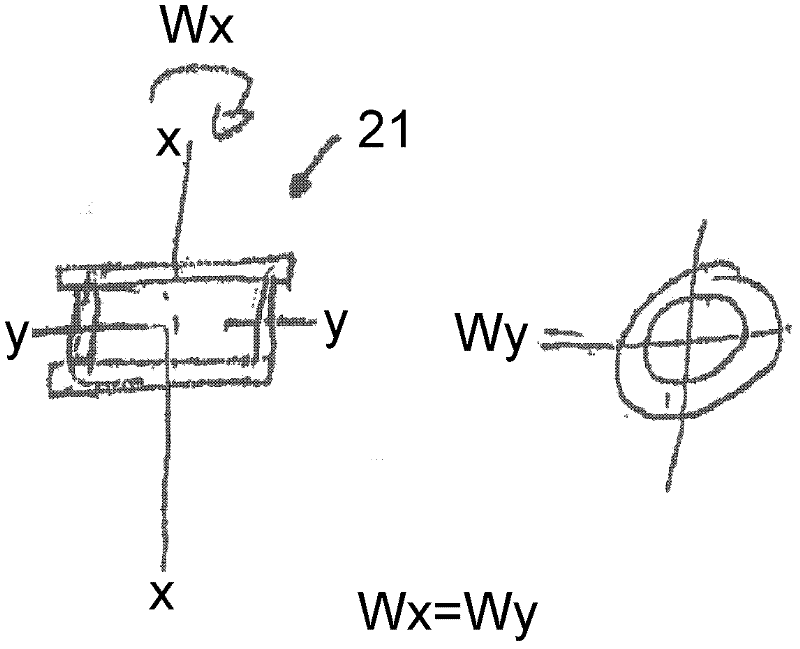
[0055] Each truss bar 21 can also be made of a welded structure consisting of four plates, as figure 2 as shown in . figure 2 shows from figure 1 Sectional view A-A. The resistance moment Wx about the X-axis x is as large as the resistance moment Wy about the Y-axis y and corresponds to a circular pipe section. A tubular lattice bar 21 is thus simulated and a "fl...


PUM


Abstract

The present invention relates to a boom element for a telescopic boom, particularly a telescopic shot or a telescopic boom base section, wherein the boom element has cupped corner pieces and lattice bars, and the cupped corner pieces are interconnected by means of the lattice bars, wherein the lattice bars are arranged in a framework, at a right angle with respect to the corner pieces, and / or at an angle different from a right angle, particularly at an acute or obtuse angle, with respect to the corner pieces, and the corner pieces and the lattice bars form a substantially box-shaped hollow structure.

Description

technical field [0001] The invention relates to a boom element for a telescopic boom, in particular a telescopic joint or a telescopic boom joint, a telescopic boom and a construction vehicle. Background technique [0002] In wind power plants, it is simultaneously desired to have a high hub height of the wind rotor in order to obtain as uniform a wind force as possible on the rotor blades. The maximum achievable hub height is therefore a characteristic value for the required lifting devices, generally mobile cranes with telescopic booms, when installing wind power plants. [0003] Based on the requirement to provide very large boom systems with long booms, the problem arises that conventional telescopic booms are too heavy. However, a telescopic boom has the advantage over a boom made of normal lattice elements that it can be quickly transferred from the transport position to the working position and requires much less space for installation. Another important advantage l...

Claims


Application Information

Patent Timeline
IPC IPC(8): B66C23/687B66C23/70
CPCB66C23/72B66C23/707
Inventor 汉斯-迪特尔·威廉
Owner LIEBHERR WERK EHINGEN
Why Eureka
Try Eureka