
Tetragonal prismatic light wave band hidden device constructed by utilizing anisotropic medium

An anisotropic and magnetic anisotropic technology, applied in the field of visible light stealth, can solve the problems of non-stealth, complicated device, impact, etc., and achieve the effect of stable performance, simple structure and easy realization

Active Publication Date: 2012-05-02
ZHEJIANG UNIV
View PDF2 Cites 21 Cited by
  • Summary
  • Abstract
  • Description
  • Claims
  • Application Information

AI Technical Summary

Problems solved by technology

[0002] Stealth has always been an ideal of human beings for a long time, but stealth technology has not been realized for a long time
The existing stealth technology is mainly in the microwave band, coating the surface of the object with materials that can absorb radar waves to prevent the target from being detected by the radar, so as to achieve invisibility. However, this technology is not true stealth, and in the visible light band, the object is still visible. of
In the optical band, the existing stealth technology is mainly military camouflage, etc., however, this is only a kind of camouflage rather than disappearing from sight
There is a kind of cloaking device that uses a camera and a display screen to capture objects on one side and display them on the other side, but its effect is affected by the quality of the image, and it requires extra energy, and the device is relatively complicated
There is another way to guide the light from one side to the other through the optical fiber, thereby bypassing the object in the middle, but such a device has high requirements on the optical fiber technology, and can only achieve stealth in one direction

Method used


Image

  • Tetragonal prismatic light wave band hidden device constructed by utilizing anisotropic medium
  • Tetragonal prismatic light wave band hidden device constructed by utilizing anisotropic medium
  • Tetragonal prismatic light wave band hidden device constructed by utilizing anisotropic medium

Examples


Embodiment Construction

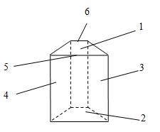
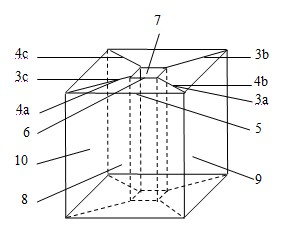
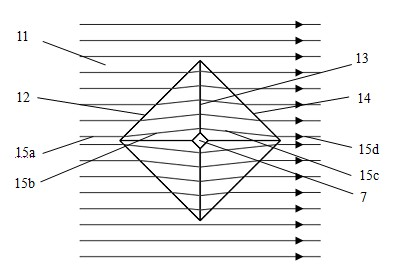
[0042] figure 1 Shown is the anisotropic dielectric unit constituting the optical band cloaking device of the present invention, and the anisotropic dielectric unit is a column with an isosceles trapezoidal cross section. figure 2 Shown is a schematic diagram of the overall structure of the optical band cloaking device of the present invention, which is composed of four anisotropic dielectric units, that is, the sides where each waist of the isosceles trapezoidal cross section of each anisotropic dielectric unit is located It is bonded together with the side where the corresponding waist of the isosceles trapezoidal cross-section of the adjacent anisotropic medium unit is located. Specifically, as figure 2 As shown, the side 3a of the anisotropic medium unit 8 is bonded to the side 4b of the adjacent anisotropic medium unit 9, and the other side 4a of the anisotropic medium unit 8 is bonded to the adjacent side 4b of the anisotropic medium unit 8. The side faces 3c of the ...


PUM


Abstract

The invention discloses a tetragonal prismatic light wave band hidden device constructed by utilizing an anisotropic medium. The tetragonal prismatic light wave band hidden device is a housing with a cavity, which is surrounded by four transparent anisotropic medium units, the transparent anisotropic medium units are prism bodies with isosceles trapezoid-shaped cross sections, and the side surface in which each waist of the cross section of each anisotropic medium unit is located and the side surface in which the corresponding waist of the cross section of the adjacent anisotropic medium unitis located are jointed together; and the side surfaces in which the lower bottom edges of the cross sections of all the anisotropic medium units are located form an outer wall of the housing by surrounding, the side surfaces in which the upper bottom edges of the cross sections of all the anisotropic medium units are located form an inner wall of the housing by surrounding, and the cavity of the housing is used for placing an object to be hidden. When light passes through the device disclosed by the invention, the anisotropic medium is used for controlling the propagation direction of the light and enabling the light to bypass the middle cavity, and the emergent direction of the light is the same with the original incident direction of the light, so that the device has a hidden effect in four directions and is suitable for a whole visible light wave band.

Description

technical field [0001] The invention relates to a square columnar optical band stealth device constructed by using an anisotropic medium, which belongs to the field of visible light stealth. Background technique [0002] Stealth has always been an ideal of human beings for a long time, but stealth technology has not been realized for a long time. The existing stealth technology is mainly in the microwave band, coating the surface of the object with materials that can absorb radar waves to prevent the target from being detected by the radar, so as to achieve invisibility. However, this technology is not true stealth, and in the visible light band, the object is still visible. of. In the optical band, the existing stealth technology is mainly military camouflage, etc. However, this is only a kind of camouflage rather than really disappearing from sight. There is a kind of stealth device that uses a camera and a display screen to capture objects on one side and display them o...

Claims


Application Information

Patent Timeline
IPC IPC(8): G02B6/00
Inventor 陈红胜郑斌
Owner ZHEJIANG UNIV
Learn More