Method for testing force characteristic of linear electric motor

A linear motor and characteristic testing technology, applied in the direction of motor generator testing, force/torque/power measuring instrument, measuring device, etc., to achieve the effect of complete functions, high reliability, and improved test accuracy

Active Publication Date: 2014-01-22
HARBIN INST OF TECH
View PDF6 Cites 1 Cited by
  • Summary
  • Abstract
  • Description
  • Claims
  • Application Information

AI Technical Summary

Problems solved by technology

[0006] Aiming at the main problems existing in various linear motor test devices at present, the present invention proposes a linear motor force characteristic test method

Method used


Image

  • Method for testing force characteristic of linear electric motor
  • Method for testing force characteristic of linear electric motor
  • Method for testing force characteristic of linear electric motor

Examples


specific Embodiment approach 1

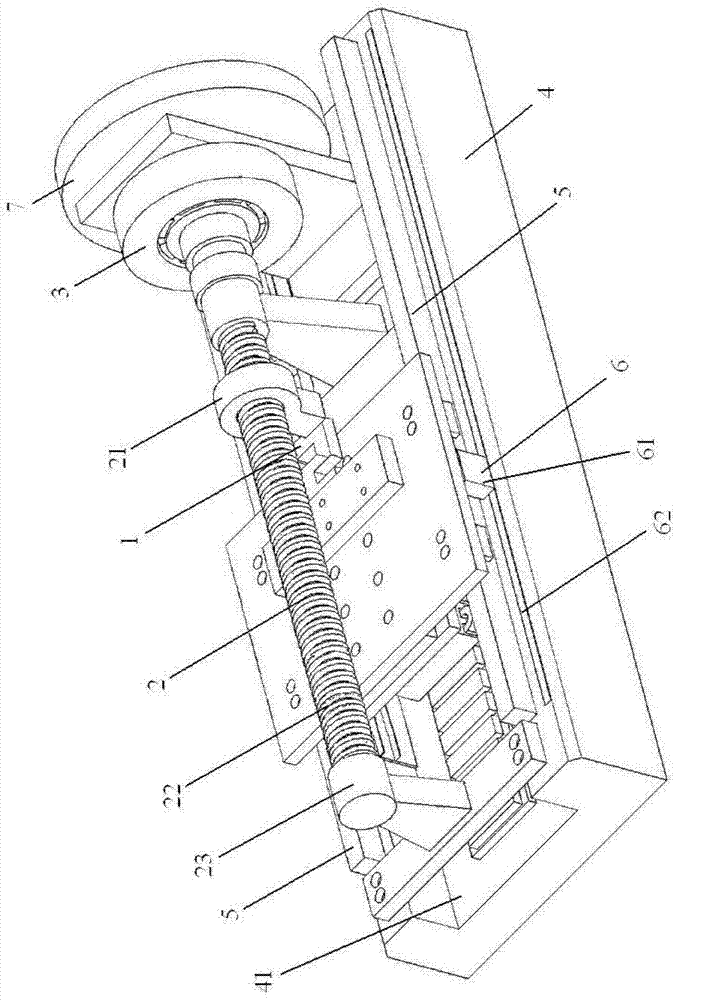
[0021] Specific implementation mode one: combine figure 1 and figure 2 This embodiment is described. In this embodiment, the linear motor force characteristic test device includes a tension pressure sensor 1, a ball screw 2, a loading servo motor 3, a base 4, a guide rail 5 and a displacement sensor 6;

[0022] Pull pressure sensor 1, the two ends of pull pressure sensor 1 are respectively connected between the nut 21 of ball screw 2 and the mover of the linear motor under test, for testing the force applied to the mover of the linear motor under test, namely Test the output force of the linear motor under test;

[0023] The ball screw 2 is used to convert the rotary motion of the loaded servo motor 3 into the linear motion of the mover of the linear motor under test; the screw 22 of the ball screw 2 is coaxially connected with the rotor of the loaded servo motor 3, and the ball screw 2 Including nut 21, screw rod 22 and fixed bracket 23;

[0024] The servo motor 3 is loa...

specific Embodiment approach 2

[0028] Specific implementation mode two: combination figure 1 Describe this embodiment, the difference between this embodiment and the specific embodiment is that it also includes an inertia flywheel 7, and the inertia flywheel 7 is located on the loading servo motor 3 to reduce the speed fluctuation during mechanical operation. The inertia flywheel 7 is installed on the rotating shaft of the screw rod 22 of the ball screw 2 and the rotor of the loading servo motor 3, and an electromagnetic clutch, magnetic coupling or torque limiter is arranged between the inertia flywheel 7 and the loading servo motor. When the rotational speed increases, the kinetic energy of the flywheel increases and the energy is stored; when the rotational speed decreases, the kinetic energy of the flywheel decreases and the energy is released. Other compositions and connection methods are the same as those in Embodiment 1.

specific Embodiment approach 3

[0029] Specific implementation mode three: combination figure 1 Describe this embodiment, the difference between this embodiment and the specific embodiment 1 or 2 is that the base 4 has a rectangular groove 41, the stator of the linear motor to be tested is fixed in the rectangular groove 41, and the platforms on both sides of the rectangular groove 41 Guide rails 5 are respectively arranged on the shoulders, and the guide members of the guide rails 5 are arranged at the bottom of the mover of the linear motor under test. The guide rail used by the mover of the tested linear motor is an air bearing guide rail, a magnetic bearing guide rail or a linear rolling guide rail. Other compositions and connection modes are the same as those in Embodiment 1 or 2.


PUM


Abstract

The invention relates to a device and a method for testing a force characteristic of a linear electric motor, which relate to the technical field of motor test, and aims at the main problems existing in various linear electric motor test devices at present. A pull pressure sensor is used for testing the output force of a linear electric motor to be tested, and is also used for testing the force applied to a rotor of the linear electric motor to be tested; a ball screw is used for converting gyroscopic motion of a loading servo motor into linear motion of the rotor of the linear electric motor to be tested, and comprises a nut, a screw rod and a fixed support; the loading servo motor is used for driving the screw rod of the ball screw to rotate and dragging the nut of the balls screw to do linear motion; a base is used for fixing a stator of the linear electric motor to be tested and the fixed support of the ball screw, so that the rotor of the linear electric motor to be tested driven by the nut of the ball screw and the stator of the linear electric motor to be tested fixed on the base are located at a normal working position of the linear electric motor; a guide rail is used for guiding and supporting the rotor of the linear electric motor to be tested to move on the base along the motion direction of the rotor of the electric motor; and a displacement sensor is used for measuring the displacement of the rotor of the linear electric motor to be tested.

Description

technical field [0001] The invention relates to the technical field of motor testing. Background technique [0002] In the field of modern processing industry, many occasions such as laser cutting, high-speed grinding machines, precision lathes, machining centers, etc. require high-speed and high-precision linear motion, while traditional methods can only be obtained by means of intermediate links such as rotating motors and ball screws. Linear motion, which inevitably has disadvantages such as large inertia, large friction, and backlash. [0003] In recent years, with the advancement of linear motor technology, more and more occasions have begun to directly apply it to obtain linear motion. Due to the direct drive technology, the linear motor has the advantages of fast speed, high acceleration, high positioning accuracy, long stroke and fast dynamic response, which just meet the requirements of high-speed precision machining technology. [0004] However, whether the perfo...

Claims


Application Information

Patent Timeline
Patent Type & Authority Patents(China)
IPC IPC(8): G01R31/34G01L5/00
Inventor 寇宝泉白相林刘孝坤唐勇斌
Owner HARBIN INST OF TECH
Why Eureka
Try Eureka