Spiral rod oil distribution energy storage plunger pump

A technology of screw and plunger pumps, which is applied in the field of hydraulic pumps, can solve the problems that the liquid and the plunger cannot be synchronized, and achieve the effect of alleviating momentum pulse and saving energy

Inactive Publication Date: 2014-02-26
胡传胜
View PDF4 Cites 0 Cited by
  • Summary
  • Abstract
  • Description
  • Claims
  • Application Information

AI Technical Summary

Problems solved by technology

[0003] The purpose of the present invention is to provide a screw rod oil distribution energy storage plunger pump to solve the problem that the liquid and the plunger cannot be synchronized when the self-priming plunger pump works at a high frequency

Method used


Image

  • Spiral rod oil distribution energy storage plunger pump
  • Spiral rod oil distribution energy storage plunger pump

Examples


Embodiment 1

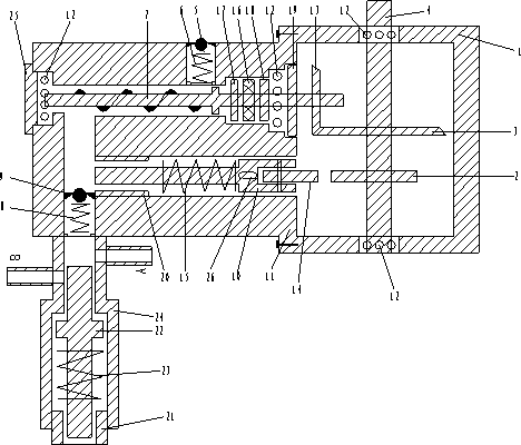
[0010] Embodiment 1: The plunger pump includes: main shaft housing 1, cam 2, driving bevel gear 3, main shaft 4, input check valve 5, input check valve spring 6, screw rod 7, output check valve spring 8, Output check valve 9, plunger 10, plunger pump casing 11, screw rod bearing 12, driven bevel gear 13, pulley 14, plunger spring 15, oil seal 16, lower gasket 17, upper gasket 18, method Lan 19, cylinder liner 20, pressure regulating hollow screw 21, sliding plug 22, sliding plug spring 23, energy storage safety valve 24, screw rod cavity screw 25, positioning keyway 26, working liquid outlet a and overpressure liquid outlet b ;

[0011] The main shaft housing 1 is connected with the plunger pump housing 11, the main shaft 4 is connected with the main shaft housing 1 through the screw bearing 12, one end of the main shaft 4 protrudes outside the main shaft housing 1, and the main shaft 4 in the main shaft housing is equipped with an active Bevel gear 3 and cam 2; the driving b...

Embodiment 2

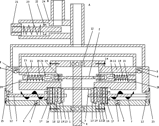
[0013] Example 2: In figure 2 Among them, two sets of schemes identical to those in Embodiment 1 are respectively installed on both sides of the main shaft 4, and the output check valve 9 of the two sets of technical schemes is jointly connected with the energy storage safety valve 24, and the outlet on the energy storage safety valve 24 The oil port a is the common oil outlet of the two groups of schemes, and the decompression outlet b is the common decompression port of the two groups of schemes. Others are the same as in Example 1.


PUM


Abstract

A spiral rod oil distribution energy storage plunger pump belongs to hydraulic pumps. A spindle box body of the plunger pump is connected with a plunger pump box body, and a driving bevel gear and a cam are installed on a spindle in the spindle box body. A plunger is installed in a plunger pump cavity of the plunger box body, a sliding wheel is arranged at the top of the plunger, a spring is installed in the middle of the plunger, and a cylinder sleeve is connected onto a plunger cavity body at the lower portion of the plunger. A driven bevel gear, a flange, screw rod bearings, an upper gasket, an oil seal and a lower gasket are sequentially connected onto a spiral rod, the spiral rod bearings are connected to the bottom of the screw rod and to the position between the upper gasket and the flange, and a spiral rod cavity screw is connected to the bottom of the spiral rod cavity. An input one-way valve spring is arranged on an input one-way valve, an output one-way valve is installed at the lower half portion of the plunger box body, a sliding plug and a sliding plug spring are installed in an energy storage safety valve, a pressure regulating hollow screw is installed at the top of the energy storage safety valve, and a normal work liquid outlet and a hyperpressure liquid outlet are arranged on the energy storage safety valve. The spiral rod oil distribution energy storage plunger pump has the advantages that a fly wheel is installed on a shaft head of a power machine, acting can be achieved by means of inertia kinetic energy of the fly wheel, and energy is saved.

Description

technical field [0001] The invention relates to a hydraulic pump, in particular to a screw rod oil distribution energy storage plunger pump. Background technique [0002] At present, the plunger pumps used by people include self-priming plunger pumps, and the plunger pumps are all constant flow pumps. The self-priming plunger pumps cannot synchronize the liquid and the plunger under the condition of high-frequency work, and the oil supply efficiency is low. At the same time, it cannot absorb the inertial kinetic energy in the working process, and has no energy-saving performance. Contents of the invention [0003] The purpose of the present invention is to provide a screw rod oil distribution energy storage plunger pump to solve the problem that the liquid and the plunger cannot be synchronized when the self-priming plunger pump works at high frequency. [0004] The purpose of the present invention is achieved in this way: the plunger pump includes: main shaft housing, ca...

Claims


Application Information

Patent Timeline
Patent Type & Authority Patents(China)
IPC IPC(8): F04B17/00
Inventor 胡传胜
Owner 胡传胜
Why Eureka
Try Eureka