Manually-operated and linearly-controlled integrated brake system
A technology of manpower control and braking system, which is applied in the direction of brakes, brake transmission devices, mechanical brake transmission devices, etc., can solve the problems of braking feeling and reliability defects, difficulty in combining multiple functions, etc., and achieve reduction requirements and save Space, the effect of reducing the required space
- Summary
- Abstract
- Description
- Claims
- Application Information
AI Technical Summary
Problems solved by technology
Method used
Image

Examples
Embodiment 1
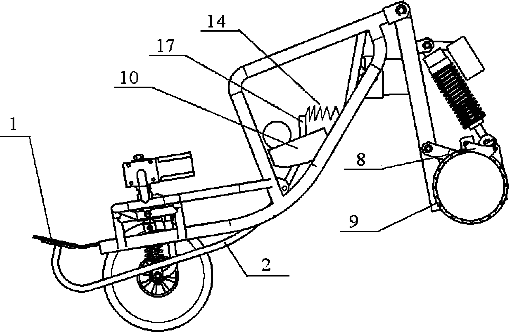
[0036] Example 1. see Figure 5 , The braking system is applied to a traditional engine-driven car, and the brake actuator adopts a mechanical structure. The brake pedal 1 and the transmission rod group 2 are welded together, installed on the vehicle frame 100 through the installation hole 4, and hidden under the bottom plate 3. The return spring 14 is installed on the vehicle frame 100 and connected to the connecting portion 17 at the rear end of the transmission rod set 2 . The first wire rope 6 is connected to the rear side of the connection part 17 of the transmission rod group 2, and is connected to the brake caliper (brake shoe 8) through the brake sheave 7, and the brake caliper (brake shoe 8) and the brake disc (brake drum) 9) Connect.
[0037] During conventional braking, the driver steps on the brake pedal 1, and the transmission rod group 2 rotates around the mounting hole 4, and the first steel wire rope 6 is tightened through the leverage ratio, and the first s...
Embodiment 2
[0040] Example 2. see Figure 6 , The braking system is applied to traditional engine-driven vehicles, and the brake actuator adopts a hydraulic structure. The brake pedal 1 and the transmission rod group 2 are welded together, installed on the vehicle frame 100 through the installation hole 4, and hidden under the bottom plate 3. The return spring 14 is installed on the vehicle frame 100 and connected to the rear side of the connecting portion 17 of the transmission rod set 2 . The transmission rod group 2 is connected to the brake master cylinder 12, the brake master cylinder 12 is connected to the brake wheel cylinder through the hydraulic pipeline 18, and the brake wheel cylinder is connected to the brake disc (or brake shoe assembly) through the brake caliper (or brake shoe assembly). Moving drum 9) is connected.
[0041] During conventional braking, the driver steps on the brake pedal 1, the transmission rod group 2 rotates around the mounting hole 4, and pulls the br...
Embodiment 3
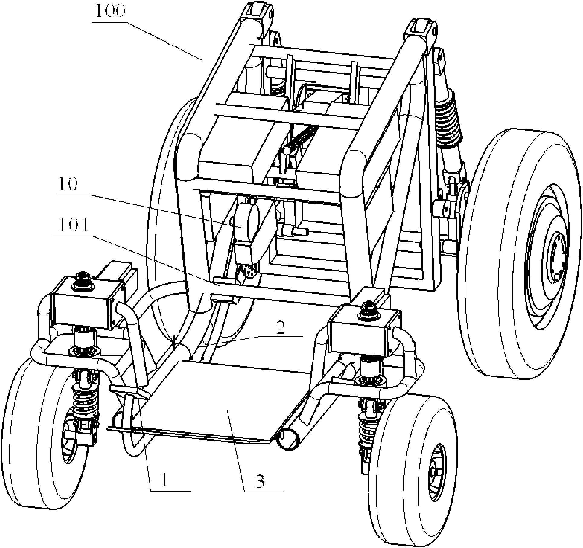
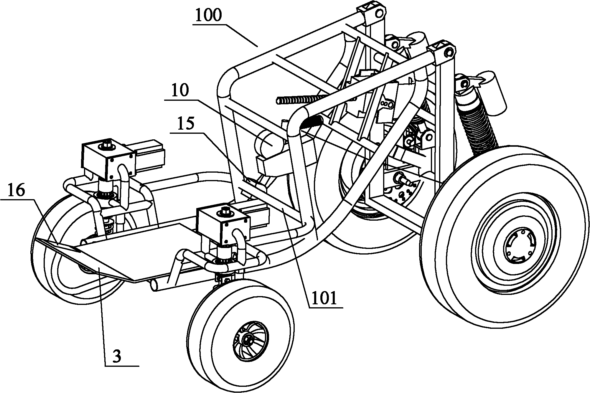
[0044] Example 3. Such as Figure 7 As shown, the brake system is used on the electric vehicle driven by the hub motor 13, and the brake actuator adopts a mechanical or hydraulic structure (see Figure 7 ).
[0045] During conventional braking, the braking process is the same as in Embodiment 1 or Embodiment 2.
[0046] During parking braking, the braking process is the same as embodiment 1 or embodiment 2.
[0047] During automatic braking, the ECU control unit receives the signal from the sensor and controls the forward and reverse rotation of the brake motor 10. The brake motor 10 is connected to the worm gear 11, and the worm gear 11 is connected to the transmission rod group 2 through the second wire rope 5, and the transmission rod group 2. Connect the brake master cylinder 12, and connect the brake wheel cylinder through the hydraulic pipeline 18. The brake wheel cylinder drives the brake caliper (brake shoe 8) to clamp the brake disc (brake drum 9) to complete autom...
PUM
 Abstract
Description
Claims
Application Information
 - Generate Ideas
- Intellectual Property
- Life Sciences
- Materials
- Tech Scout
- Unparalleled Data Quality
- Higher Quality Content
- 60% Fewer Hallucinations
Browse by: Latest US Patents, China's latest patents, Technical Efficacy Thesaurus, Application Domain, Technology Topic, Popular Technical Reports.
© 2025 PatSnap. All rights reserved.Legal|Privacy policy|Modern Slavery Act Transparency Statement|Sitemap|About US| Contact US: help@patsnap.com