
Continuous and mechanical variable valve timing adjusting device for internal combustion engine

A valve timing and mechanical adjustment technology, which is applied in the direction of valve devices, mechanical equipment, machines/engines, etc., can solve problems such as difficult reliability, complex structure, and many followers, so as to improve economy, power, and High adjustment accuracy and good reliability

Inactive Publication Date: 2012-04-25
SHANGHAI JIAO TONG UNIV
View PDF7 Cites 13 Cited by
  • Summary
  • Abstract
  • Description
  • Claims
  • Application Information

AI Technical Summary

Problems solved by technology

[0003] Through the retrieval of prior art documents, it is found that the patent application number is 200610069982.5, the publication number is CN1959072, and the name is an invention patent of a continuously variable valve timing system for an internal combustion engine controlled by electro-hydraulic control. In its specific embodiment, it can only It is difficult to control the valve opening time by controlling the falling and closing time of the valve, and the reliability and adjustment accuracy are difficult to guarantee
The patent application number is 200610169984.1, and the publication number is CN101182807, which is an invention patent named continuously variable valve lift device, which realizes continuous adjustment of valve lift and valve timing, but its structure is complex and there are too many followers. Reliability is difficult to guarantee, and it is difficult to install on the original engine

Method used


Image

  • Continuous and mechanical variable valve timing adjusting device for internal combustion engine
  • Continuous and mechanical variable valve timing adjusting device for internal combustion engine
  • Continuous and mechanical variable valve timing adjusting device for internal combustion engine

Examples


Embodiment

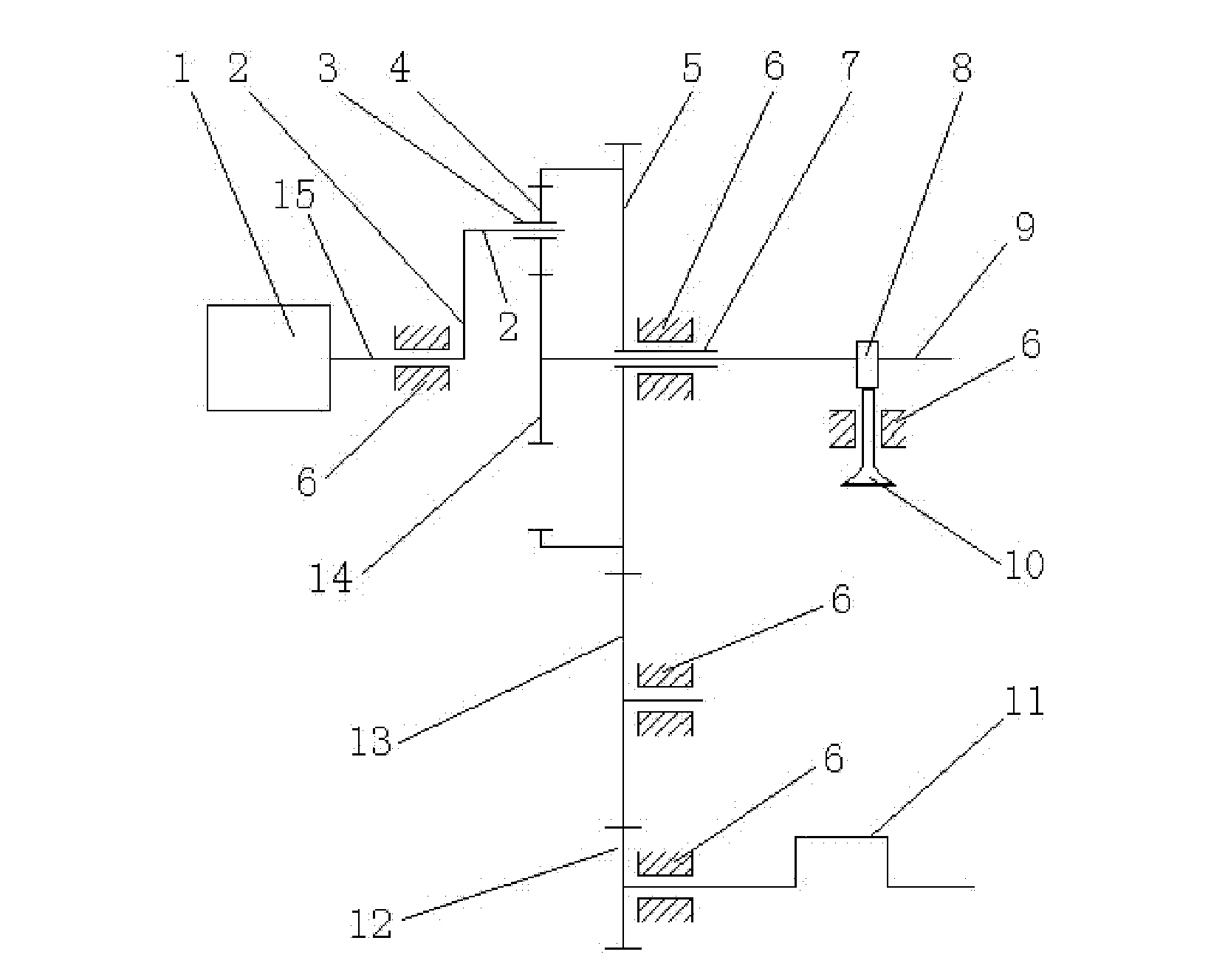
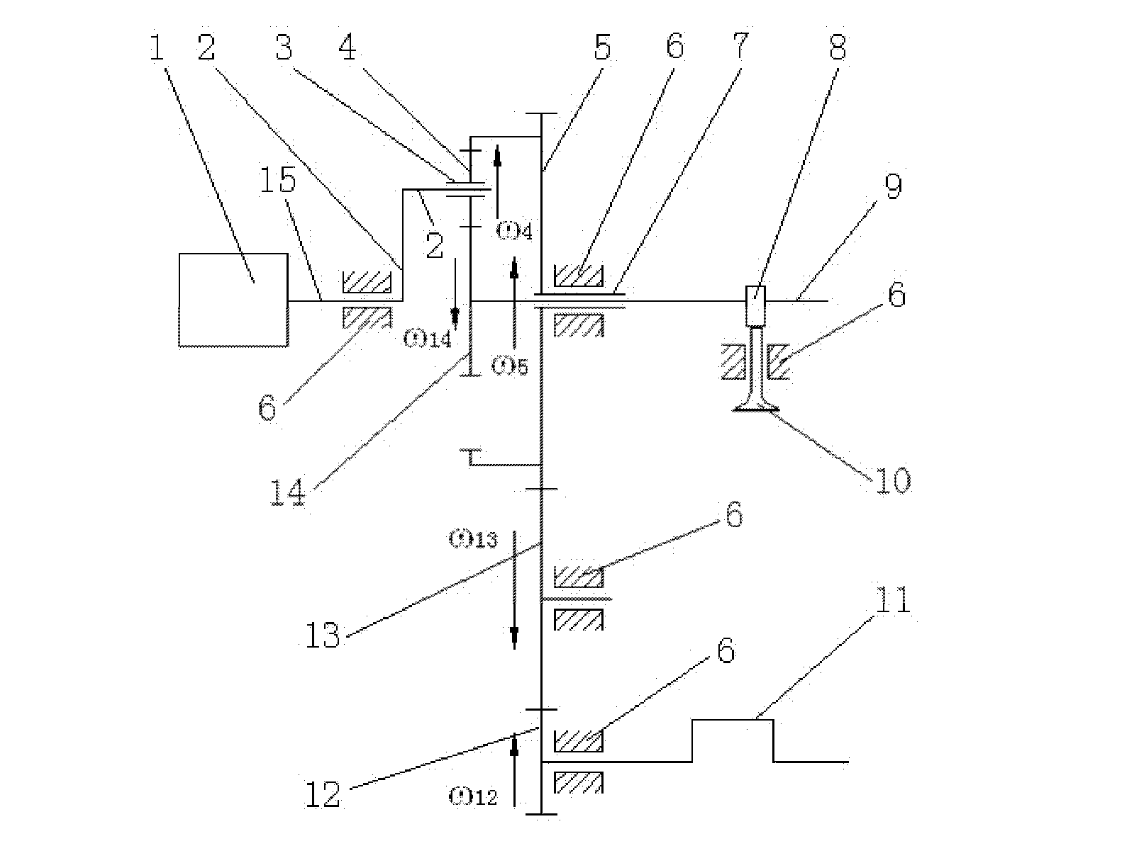
[0018] Such as figure 1 As shown, the present invention includes: internal combustion engine body 6, crankshaft 11, camshaft 9, cam 8, valve 10, driving gear 12, intermediate transmission device 13, input sun gear 5, planetary gear 4, planetary gear carrier 2, output sun gear 14. Adjusting device 1, input sun gear bushing 7, planetary gear bushing 3 and connecting shaft 15, the camshaft 9 passes through the axis of the cam 8 and is connected with the cam 8 as a whole, the valve stem of the valve 10 is in phase with the cam 8 Contact, the input sun gear sleeve 7 is installed at the axis of the input sun gear 5, the planetary gear sleeve 3 is installed at the axis of the planetary gear 4, the front end of the crankshaft 11 is installed at the axis of the drive gear 12, and the input center The ring gear of the gear 5 includes an outer ring gear and an inner ring gear. The intermediate transmission device 13 is respectively meshed with the drive gear 12 and the input sun gear 5 o...


PUM


Abstract

The invention provides a continuous and mechanical variable valve timing adjusting device for an internal combustion engine, belonging to the technical field of internal combustion engines. The device comprises a crankshaft, a cam shaft, a cam, a driving gear, an intermediate gearing, an input center gear, a planet gear, a planet gear carrier, an output center gear and an adjusting device, wherein the front end of the crankshaft is installed at the axle center of the driving gear; the intermediate gearing is meshed with the driving gear and an outer gear ring of the input center gear respectively; the planet gear is meshed with an inner gear ring of the input center gear and the output center gear respectively; the front end of the cam shaft is installed at the axle center of the output center gear; and the adjusting device is connected with the planet gear carrier by a connecting shaft. In the working process of the device, when the planet gear carrier rotates in a certain direction,the rotating speed of the output center gear is increased or decreased, thus changing the rotation phase between the cam shaft and the crankshaft and realizing adjustment of valve timing. The device has reasonable design, simple structure, good reliability and higher adjustment precision and is easy to add on the original engine.

Description

technical field [0001] The invention relates to a valve adjustment device in the field of internal combustion engines, in particular to a continuously variable valve timing mechanical adjustment device for internal combustion engines. Background technique [0002] Energy saving and emission reduction is a major topic of common concern in the field of internal combustion engines. The valve timing of the engine directly affects the charging efficiency of the engine, and thus has a very important impact on the combustion process in the cylinder of the engine. The variable valve timing technology optimizes the charge into the cylinder by adjusting the valve timing of the engine under different operating conditions, thereby improving the power and economy of the engine. The ideal valve timing law should be able to adjust properly in time according to the change of engine operating conditions, and this adjustment should be continuous and have sufficient flexibility. When the eng...

Claims


Application Information

Patent Timeline
IPC IPC(8): F01L1/344
CPCF01L1/352
Inventor 彭海勇崔毅邓康耀王绍明
Owner SHANGHAI JIAO TONG UNIV
Learn More